Power Transmission System and Vehicle With It

a technology of transmission system and transmission device, which is applied in the direction of fluid gearing, transportation and packaging, gearing, etc., can solve the problems of poor protection of exposed brakes, low transaxle, and early wear of brakes, so as to ensure the compactness of transaxles, reduce the number of parts, the number of manufacturing processes, and the effect of cost reduction

Active Publication Date: 2007-07-05
KANZAKI KOKYUKOKI MFG
View PDF9 Cites 28 Cited by
  • Summary
  • Abstract
  • Description
  • Claims
  • Application Information

AI Technical Summary

Benefits of technology

[0023] Preferably, in the power transmission system of the second aspect, a pair of reservoir tanks are connected to the respective housings of the transaxles so as to regulate volumes of the respective fluid sumps in the housings. The reservoir tanks are fluidly connected to the respective brake chambers. Therefore, the reservoir tanks used for regulating volumes of the fluid sumps in the housings are also used for supplying fluid to the respective wet brakes, thereby reducing the number of parts, the number of manufacturing processes, and costs, while ensuring the compactness of the transaxles.
[0024] Preferably, in the power transmission system of the second aspect, the hydraulic pumps in the respective transaxles are variable displacement hydraulic pumps with respective movable swash plates. The cover serves as a guide member for the movable swash plates, thereby saving the number of parts, the number of manufacturing processes, and costs.
[0025] Preferably, in the power transmission system of the second aspect, the hydraulic pumps in the respective transaxles are variable displacement hydraulic pumps with respective movab...

Problems solved by technology

The lowered transaxles may interfere with the working device or the working power transmission mecha...

Method used


Image

  • Power Transmission System and Vehicle With It
  • Power Transmission System and Vehicle With It
  • Power Transmission System and Vehicle With It

Examples


Embodiment Construction

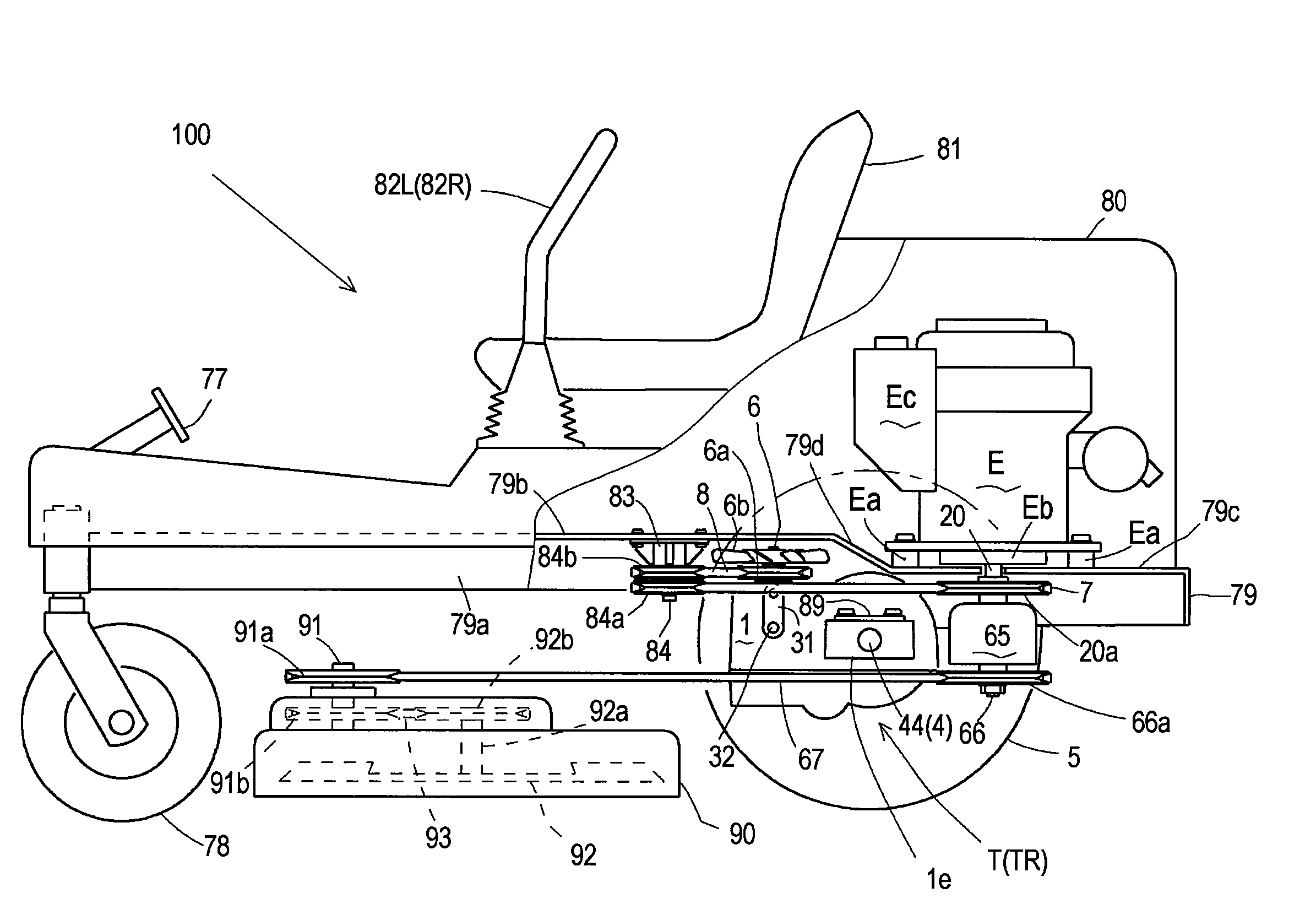
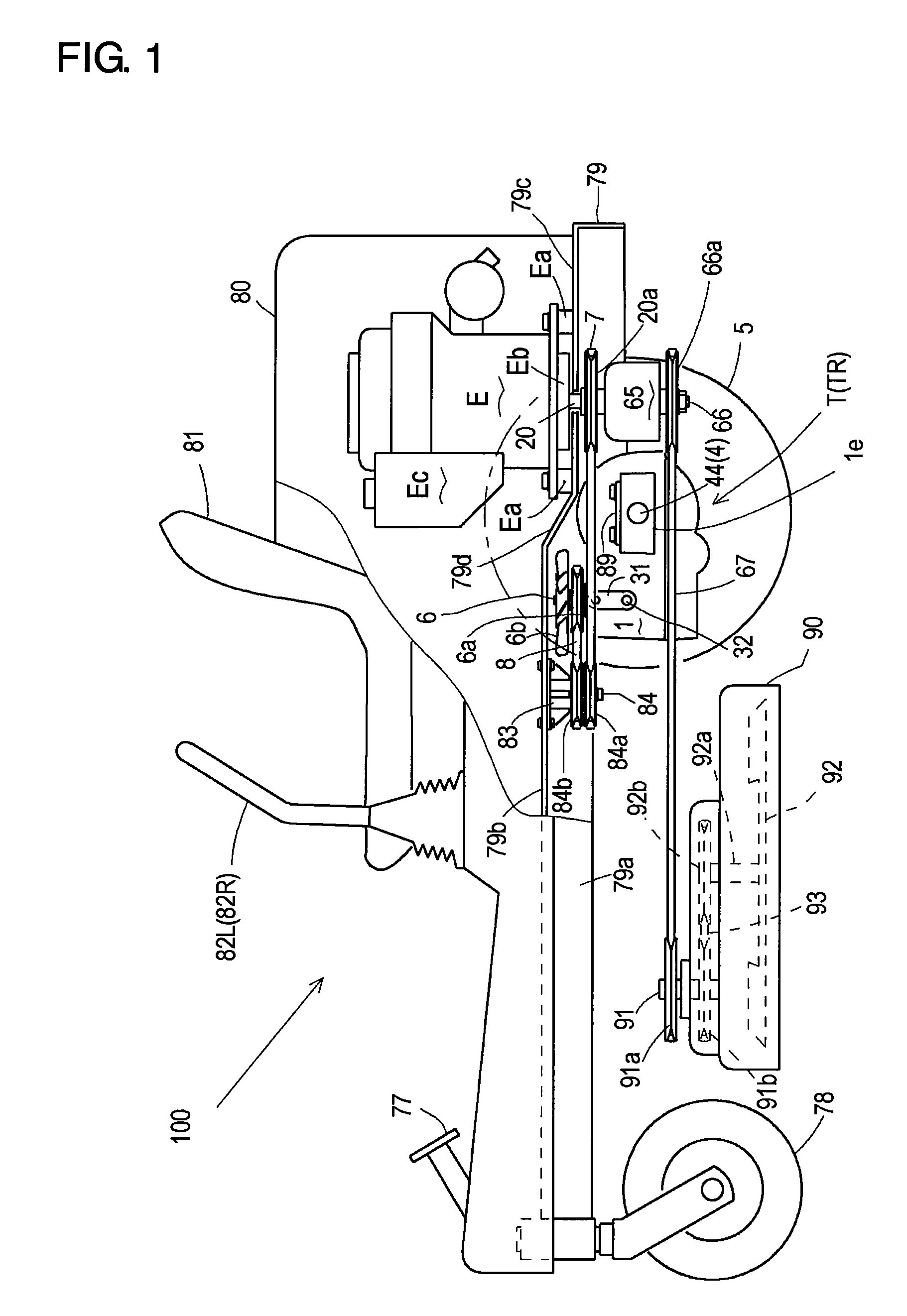
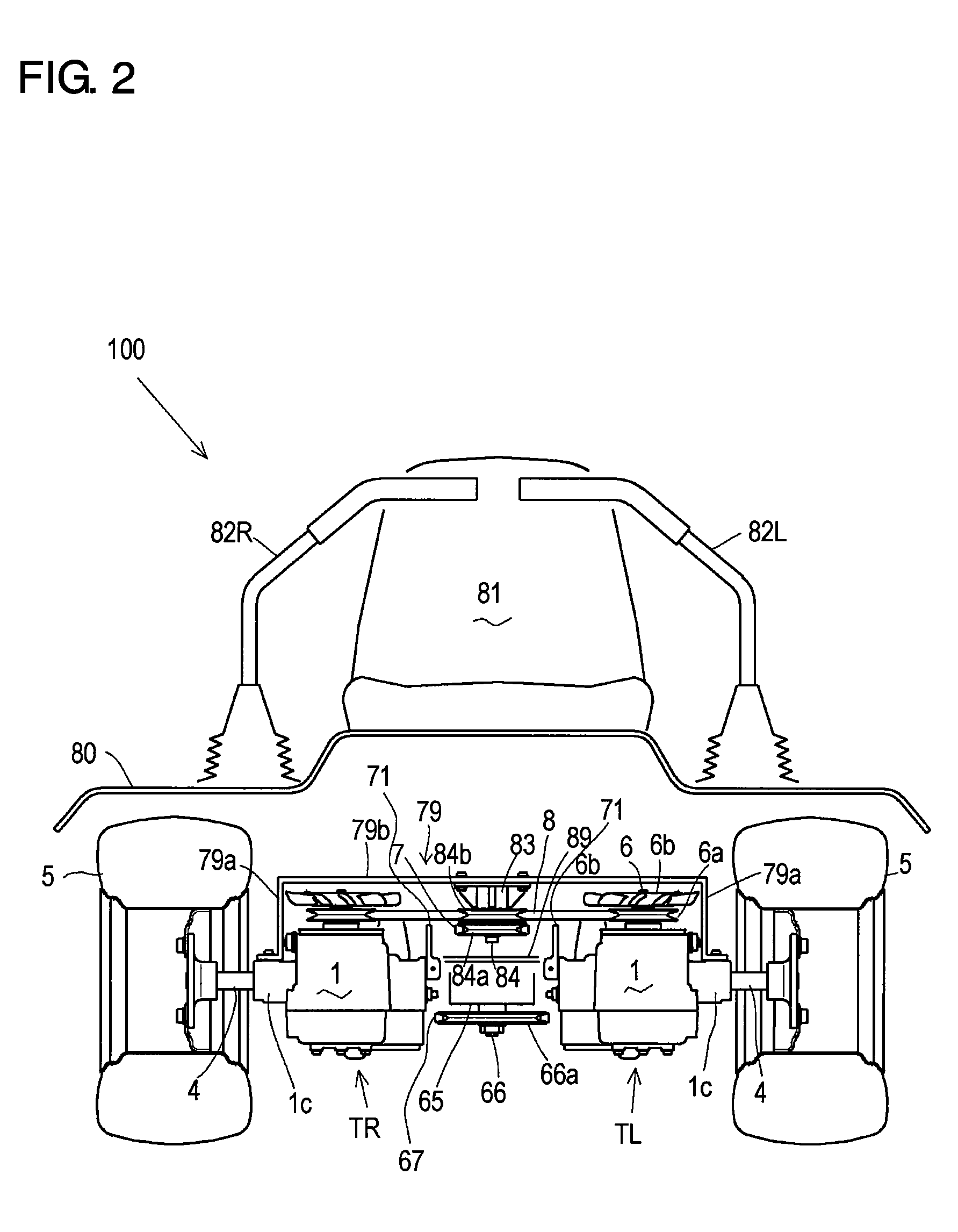
[0063] Referring to FIGS. 1 to 5, description will be given of a general configuration of a working vehicle 100 serving as an embodiment of a hydraulically driven working vehicle equipped with a power transmission system of the invention.

[0064] Working vehicle 100 includes a fore-and-aft extended vehicle frame 79. Vehicle frame 79 is bent into a vertically reversed U-like shape in a sectional front view, so as to have a pair of left and right vertical plate portions 79a and a horizontal plate portion 79b between left and right vertical plate portions 79a. Further, as shown in FIG. 1, a rear horizontal plate portion 79d is formed between left and right vertical plate portions 79a behind horizontal plate portion 79b so as to be lower than horizontal plate portion 79b.

[0065] As shown in FIGS. 1 and 3, horizontal plate portion 79b and rear horizontal plate portion 79d are connected to each other through a sloped plate portion 79c. The purposes of the slope of sloped plate portion 79c ...


PUM


Abstract

A working vehicle comprises: a vehicle frame; a prime mover mounted on an upper surface of a first portion of the vehicle frame; a pair of left and right transaxles juxtaposed below the vehicle frame, the left and right transaxles having respective single axles so as to individually and reversibly rotatably driving left and right drive wheels; a working device disposed below the vehicle frame; an output shaft of the prime mover extended downward from the first portion of the vehicle frame; a traveling belt transmission disposed below the vehicle frame and extended from the output shaft to the pair of left and right transaxles; a working belt transmission disposed below the vehicle frame and extended from the output shaft to the working device; a counter shaft for the traveling belt transmission extended downward from a second portion of the vehicle frame; and a pair of upper and lower pulleys provided on the counter shaft, wherein a belt looped over the lower pulley is extended from the output shaft of the prime mover, and a belt looped over the upper pulley is extended to the left and right transaxles.

Description

BACKGROUND OF THE INVENTION [0001] 1. Field of the Invention [0002] The invention relates to a power transmission system comprising: right and left independent transaxles for driving respective right and left axles; and a working power clutch unit incorporating a working power clutch. The invention also relates to a working vehicle equipped with the power transmission system. [0003] 2. Related Art [0004] Conventionally, there is a well-known working vehicle equipped with right and left independent transaxles for driving respective right and left axles, such as pedestrian-controlled lawn mowers as disclosed in U.S. Pat. No. 5,127,215A (reference 1) and WO 97 / 15764 (reference 2). This type working vehicle is advantageous in its compactness, its large space for a working device, and its ability of sharp turning (i.e., zero-turning). [0005] In each of the vehicles disclosed in the references 1 and 2, an engine serving as a prime mover is disposed so as to extend its output shaft vertica...

Claims


Application Information

Patent Timeline
IPC IPC(8): A01D43/00F16H59/00
CPCA01D69/06A01D69/03F16H39/14F16H7/02
Inventor IIDA, MASARUISHINO, FUMITOSHITSUKAMOTO, MICHIOKAWAKAMI, MANABU
Owner KANZAKI KOKYUKOKI MFG
Why Eureka
Try Eureka