Refrigerating cycle

a technology of refrigerating cycle and hammer, which is applied in the direction of refrigeration components, transportation and packaging, light and heating equipment, etc., can solve the problems of further affecting the effect of rushing noise and noise, and achieve the effect of reducing rushing noise or water hammer noise, easing inflow, and reducing unpleasant nois

Inactive Publication Date: 2007-07-05
DENSO CORP
View PDF4 Cites 15 Cited by
  • Summary
  • Abstract
  • Description
  • Claims
  • Application Information

AI Technical Summary

Benefits of technology

[0012] A first aspect of the present invention is characterized by making a differential pressure between an inlet refrigerant pressure and outlet refrigerant pressure of a second evaporator solenoid valve (or second evaporator downstream solenoid valve) when starting or stopping a second evaporator during operation of a first evaporator smaller than the differential pressure when operating only the first evaporator, then opening or closing the second evaporator solenoid valve (or second evaporator downstream solenoid valve). By reducing the differential pressure causing the unpleasant noise, the unpleasant noise can be reduced.
[0013] A second aspect of the present invention is characterized in that the second evaporator solenoid valve (or second evaporator downstream solenoid valve) is a pilot type solenoid valve. The opening operation and closing operation of a pilot type solenoid valve is performed in two stages, so rushing noise becomes further harder to be caused. Further, a pilot type solenoid valve operates a pilot valve by the pressure difference before and after it in a second stage opening / closing operation, so a spring force relating to the pilot valve or an electromagnetic force countering it may be set smaller than the corresponding forces of a usual direct acting solenoid valve. For this reason, a pilot type solenoid valve can be made smaller than a usual direct acting type solenoid valve.
[0016] A fifth aspect of the present invention is characterized by reducing a working capacity of the compressor so as to reduce the differential pressure. Due to this, addition of special devices becomes unnecessary.
[0017] A sixth aspect of the present invention is characterized in that the second pressure reducer has a variable aperture for opening or cutting off the inflow of refrigerant to the second evaporator and gradually opens or shuts the variable aperture when starting or stopping the second evaporator during operation of the first evaporator. By gradually opening or shutting the variable aperture, it becomes possible to ease the inflow or cutoff of refrigerant to the second evaporator and thereby reduce the rushing noise or water hammer noise.
[0018] A seventh aspect of the present invention is characterized in that the refrigerant is CO2 raised to a critical pressure or more. When using CO2 raised to a critical pressure or more for the refrigerant, the differential pressure becomes remarkably larger than during use of a usual refrigerant R134a and the rushing noise or water hammer noise becomes larger. For this reason, when the refrigerant is the supercritical state CO2, the effect of employing the present invention (reduction of unpleasant noise) becomes remarkable.

Problems solved by technology

The opening operation and closing operation of a pilot type solenoid valve is performed in two stages, so rushing noise becomes further harder to be caused.

Method used


Image

  • Refrigerating cycle
  • Refrigerating cycle
  • Refrigerating cycle

Examples


first embodiment

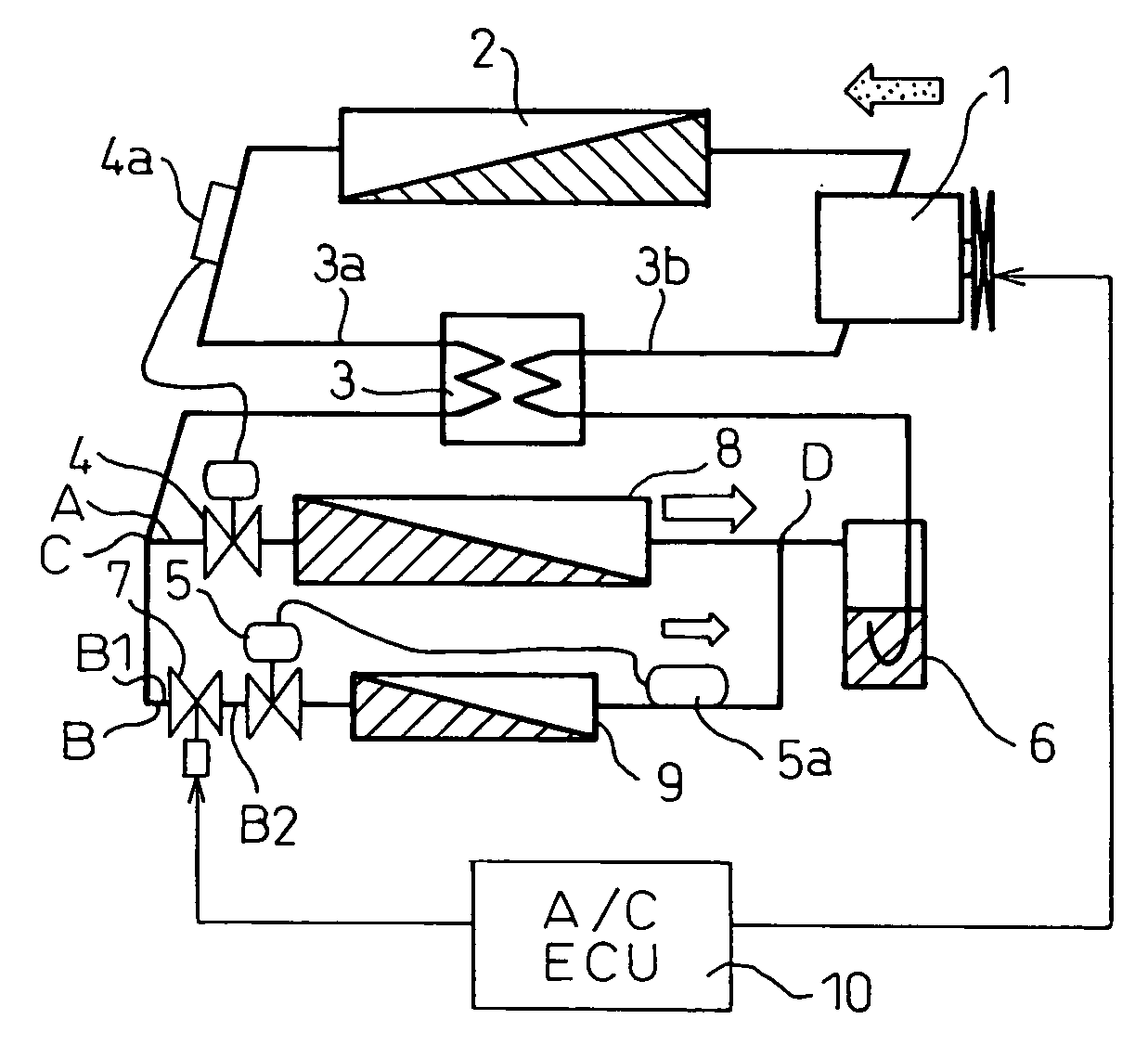
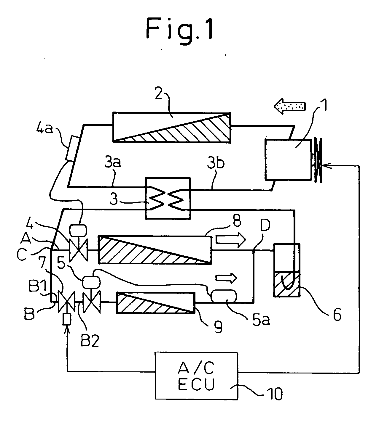
[0026]FIG. 1 is a view of the configuration of a refrigeration cycle for vehicle air-conditioning showing a first embodiment of the present invention. This refrigeration cycle uses a refrigerant comprised of CO2 having a high pressure of the critical pressure or more (supercritical state). Therefore, this refrigeration cycle forms a supercritical refrigeration cycle.

[0027] A compressor 1 obtains drive power from a not shown vehicle engine through an electromagnetic clutch (not shown) to suck in and compress the refrigerant. Note that the compressor 1 may be any of a fixed capacity type compressor operating continuously by operation of an electromagnetic clutch or a variable capacity type compressor able to be changed in discharge capacity.

[0028] A discharge side of the compressor 1 is provided with a radiator 2 forming an outside unit. This radiator 2 exchanges heat between a discharged refrigerant in the high temperature, high pressure supercritical state discharged from the comp...

second embodiment

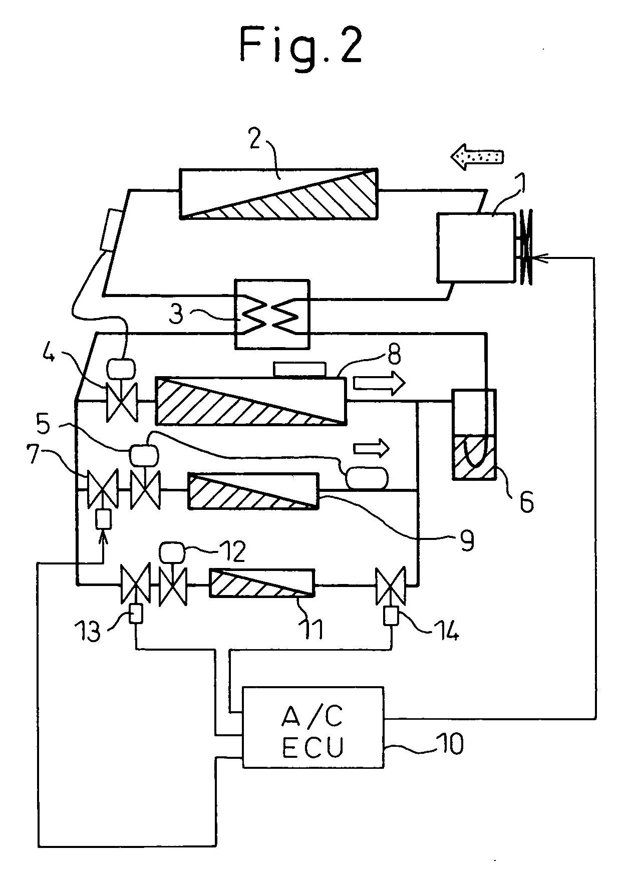
[0057] Next, a second embodiment according to the present invention will be explained with reference to FIG. 2. The second embodiment adds to the first embodiment a set of solenoid valves (two, for inlet and outlet), a pressure reducer, and an evaporator. For this reason, the second embodiment will be explained focusing on the locations different from the first embodiment.

[0058] Reference numeral 11 indicates a vehicle refrigerator evaporator (hereinafter referred to as the “third evaporator”). Reference numeral 13 indicates a third evaporator inlet solenoid valve, while 14 indicates a third evaporator outlet solenoid valve. Normally, the two solenoid valves of 13 and 14 are simultaneously turned on and off. Reference numeral 12 indicates a third pressure reducer.

[0059] If suddenly operating the third evaporator while the first evaporator is operating, rushing noise is generated in the third pressure reducer 12. The second embodiment can be configured by reading the “third” in the...

third embodiment

[0063] Instead of the second pressure reducer 5 of the first embodiment, it is also possible to employ a pressure reducer having a variable aperture function. This pressure reducer gradually changes the cross-sectional area of the flow channel of the refrigerant to the second evaporator 9. This type of slow change can be provided by the response characteristics of the variable aperture or by the control unit 10 for controlling the actuator for driving the variable aperture. The second pressure reducer 5 has a variable aperture for opening or closing the flow of refrigerant to the second evaporator 9. When starting or stopping the second evaporator 9 while the first evaporator 8 is operating, it gradually opens or closes the variable aperture. By gradually opening or closing the variable aperture, the refrigerant smoothly flows or is cut off and the rushing noise or water hammer noise can be reduced. A pressure reducer with such a variable aperture function can be employed in additio...


PUM


Abstract

A refrigeration cycle not generating unpleasant noise when starting or stopping a second evaporator while a first evaporator is operating is provided. The refrigeration cycle of the present invention is characterized by making a differential pressure between an inlet refrigerant pressure and outlet refrigerant pressure of a second evaporator solenoid valve when starting or stopping the second evaporator during operation of the first evaporator smaller than the differential pressure when operating only the first evaporator, then opening or closing the second evaporator solenoid valve.

Description

TECHNICAL FIELD [0001] The present invention relates to a refrigeration cycle provided with a plurality of evaporators which is suitable for use for a supercritical refrigeration cycle using a CO2 (carbon dioxide) refrigerant or other such refrigerant where the high pressure becomes the critical pressure or more (supercritical state). BACKGROUND ART [0002] The inventors previously proposed a refrigeration cycle, as shown in FIG. 1, configured by a plurality of evaporators 8, 9 connected in parallel. In the configuration of FIG. 1, a first pressure reducer 4 reducing the pressure of the refrigerant flowing into a first evaporator 8 among a plurality of evaporators 8, 9 is configured by a temperature type valve mechanism. [0003] Further, by controlling the opening degree of the first pressure reducer 4 based on the refrigerant temperature of the radiator outlet, the outlet refrigerant pressure of the radiator 2 is controlled to become a target pressure determined by the radiator outle...

Claims


Application Information

Patent Timeline
Patent Type & Authority Applications(United States)
IPC IPC(8): F25B41/04
CPCB60H1/00885F25B2700/21175B60H2001/00957F25B5/02F25B9/008F25B40/00F25B41/043F25B41/062F25B2309/061F25B2341/063F25B2500/18F25B2500/26F25B2500/27F25B2600/17F25B2600/21F25B2600/23F25B2600/2513F25B2700/2102B60H2001/00949F25B41/22F25B41/33
Inventor MATSUNAGA, KENTOMATSU, YOSHITAKA
Owner DENSO CORP
Why Eureka
Try Eureka