Icemaker and method for controlling the same

Active Publication Date: 2007-07-05
LG ELECTRONICS INC
View PDF12 Cites 26 Cited by
  • Summary
  • Abstract
  • Description
  • Claims
  • Application Information

AI Technical Summary

Benefits of technology

[0017] An object of the present invention is to provide an icemaker and a method for controlling the same, which has an improved structure to make a lot of ice in a short time.
[0018] Another object of the present inventio

Problems solved by technology

Thereby, the configuration of the conventional icemaker may be complicated and production cost thereof will be high.
Thus, large space should be secured near the ice tray for the rotation of the over fill detection mechanism and the ice tray cannot but be fabricated relatively small.
It causes a problem that many ices cannot be made in a short time

Method used


Image

  • Icemaker and method for controlling the same
  • Icemaker and method for controlling the same
  • Icemaker and method for controlling the same

Examples


first embodiment

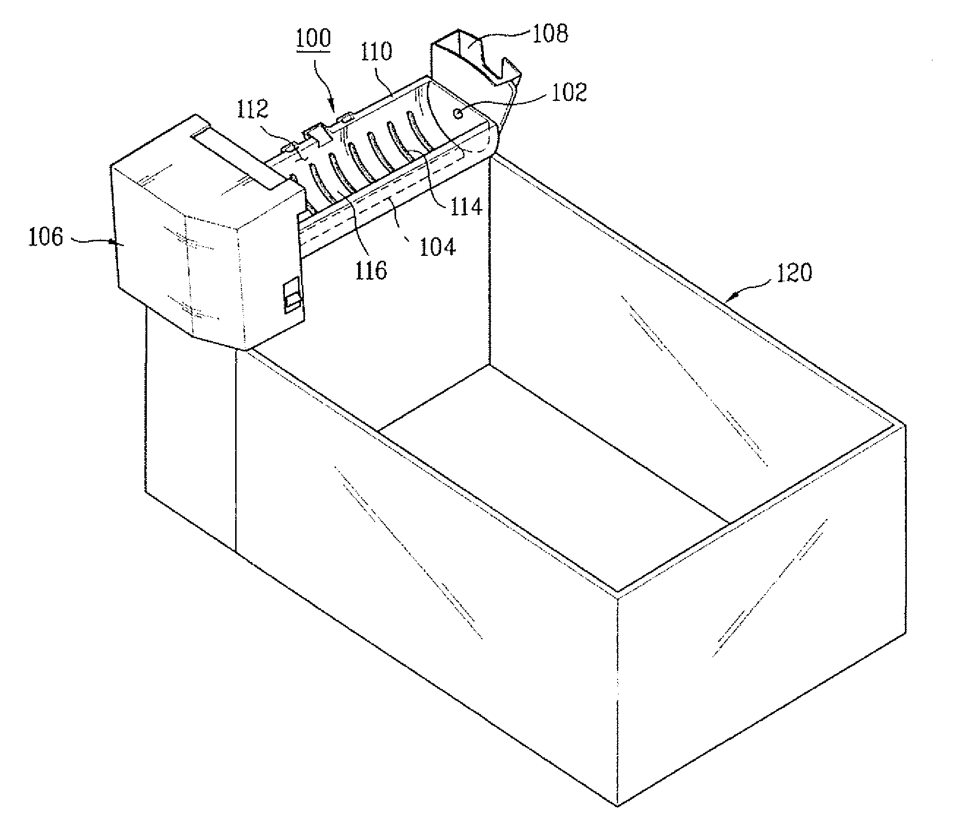
[0062]FIGS. 4 and 5 illustrate the icemaker in accordance with the present invention.

[0063] In accordance with the first embodiment of the present invention, an ice tray provided in the icemaker 100 may be rotatable, unlike the conventional icemaker, to utilize the weight of ice during the ice ejecting and to reduce energy needed for separating the ice from the ice tray 110. A separation / ejecting device, which helps the ice ejected by the rotation of the ice tray 110, is provided in the icemaker 100 of the present invention. The separation / ejecting device independently or combinatively applies heat or kinetic energy to a boundary between the ice and the ice tray to efficiently help the ice ejected when the ice tray 110 rotates.

[0064] The ice making chamber 112 receives water to make ice. For example, the ice making chamber 112 may have a semi-cylindrical shape with an opened upper part. As shown in FIG. 4, one ice making chamber 112 may be provided in the ice tray 110 or two ice ma...

second embodiment

[0081] an icemaker in accordance with the present invention will be described.

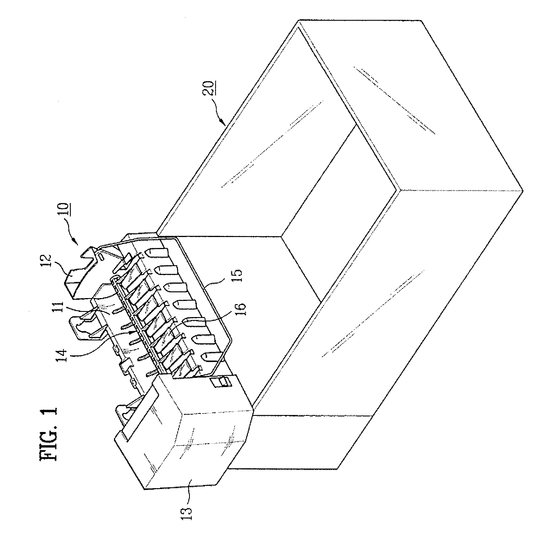
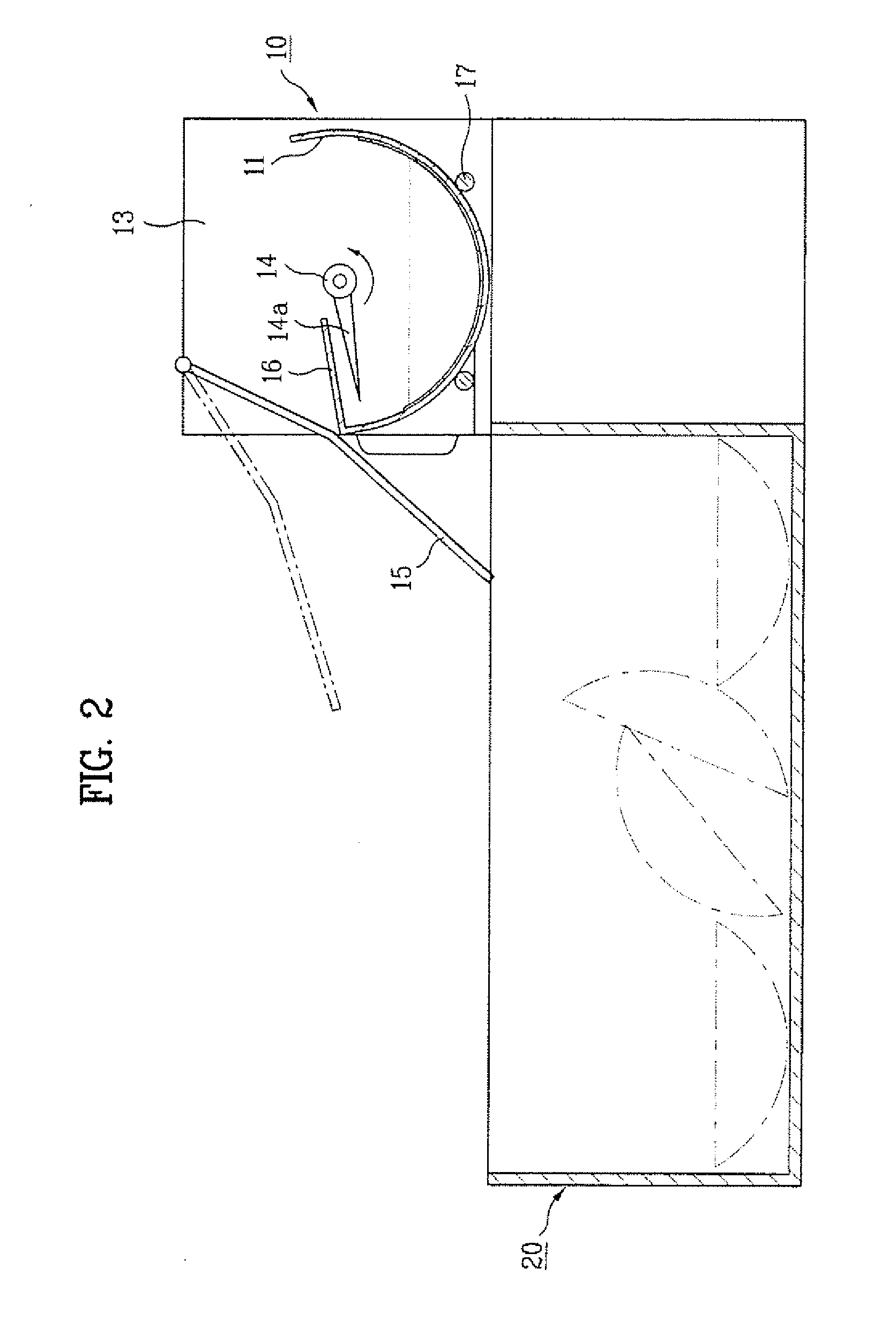
[0082] FIGS. 6 to 9 illustrate an ice tray of the icemaker in accordance with the second embodiment of the present invention.

[0083] It is preferred that configurations of an ice tray 110, an operation device 106, a heater 104 and the like provided in the icemaker of the second embodiment are the same as those of the first embodiment.

[0084] Thus, an ejector 250, which is a different configuration from the first embodiment, will be described in detail.

[0085] In accordance with the second embodiment of the present invention, it is preferred that an ejector 250 is provided in the icemaker to eject the ice made in an ice making chamber 112.

[0086] The ejector 250 will be described in more detail.

[0087] The ejector 250 of the icemaker in accordance with the second embodiment of the present invention is rotatably provided in an upper portion of the ice making chamber 112. As rotating, the ejector 250 pushes t...

third embodiment

[0099] Next, the ice maker in accordance with the present invention will be described.

[0100]FIG. 10 illustrates an ice tray of the icemaker in accordance with the third embodiment of the present invention.

[0101] It is preferred that configurations of an ice tray 110, an operation device 106, a heater 104 and the like provided in the icemaker of the third embodiment are the same as those of the first and second embodiment.

[0102] Thus, an ejector 350, which is a different configuration from the first and second embodiment, will be described in detail.

[0103] It is preferred that the ejector 350, like the first and second embodiment, is provided in each ice making chamber 112 of the ice maker 100. That is, if one ice making chamber 112 is formed in the icemaker 100, the ejector 350 is rotatably provided in one ice making chamber 112. If more than two columns of ice making chambers 112 are provided, the ejector 350 is rotatably provided in each ice making chamber 112.

[0104]FIG. 11 il...


PUM


Abstract

An icemaker and a method for controlling the same are disclosed. An object of the present invention is to provide an icemaker and a method for controlling the same, which has an improved structure to make a lot of ice in a short time. an icemaker includes an ice tray rotatable with at least one column of ice making chambers formed therein to make ice; an ejector rotatably provided in each ice making chamber to eject the ice formed in the ice making chamber; an operation device which rotates the ice tray; and a separation device which separates the ice from the ice tray. The separation device may be a heater which heats the ice. Preferably, the heater is operated until adhesive force which acts between the ice and the ice tray is smaller than pushing force in which the ejector pushes the ice.

Description

[0001] This application claims the benefit of the Patent Korean Application No. 10-2005-0124880, filed on Dec. 16, 2005, which are hereby incorporated by reference as if fully set forth herein. BACKGROUND OF THE INVENTION [0002] 1. Field of the Invention [0003] The present invention relates to an icemaker, more particularly, to an icemaker having a simple structure, which can eject ice from an ice tray with less energy, and a method for controlling the same. [0004] 2. Discussion of the Related Art [0005] In general, a household refrigerator / freezer has a freezing chamber and a refrigerating chamber. The refrigerating chamber keeps its temperature at 3˜4 degree. C to preserve food and various vegetables fresh. The freezing chamber keeps its temperature at a sub-zero, which is below 0 degree. C, to preserve frozen meat and frozen food. [0006] Recently, a household refrigerator is sold with various functions including an icemaker which automatically make ice without a consumer's additi...

Claims


Application Information

Patent Timeline
IPC IPC(8): F25C5/08F25C1/00
CPCF25C1/04F25C5/08F25C2600/04F25C2400/06F25C2305/022F25C2305/024F25C1/24
Inventor JEONG, KYUNG HANJEONG, IN CHULLEE, NAM GI
Owner LG ELECTRONICS INC
Why Eureka
Try Eureka