Non-destructive stringer inspection apparatus and method

a stringer inspection and non-destructive technology, applied in the direction of structural/machine measurement, measurement devices, instruments, etc., can solve the problems of inability to disassemble, time-consuming manual scanning of structures, prone to human error, and inability to accurately measure or sense the position, etc., to achieve the effect of accurate position measurement or sensing

Active Publication Date: 2007-07-05
THE BOEING CO
View PDF23 Cites 29 Cited by
  • Summary
  • Abstract
  • Description
  • Claims
  • Application Information

AI Technical Summary

Benefits of technology

[0011] Magnetic coupling holds the inspection device on the structure under inspection on opposite sides for through transmission inspection. The first probe of the inspection device rides along the outside of the hat stringer while the second probe rides below the hat stringer or inside the hat stringer. The magnetic coupling along with the configuration of the inspection device keep inspection sensors, such as ultrasonic transducers or x-ray sources and detectors, are aligned to inspect the hat stringer as the inspection device moves along the length of the hat stringer. The magnetic coupling keeps the transducers coupled and in physical contact with the surfaces of the structure. Keeping the transducers coupled to the structure is important to ensure reliable inspection, such as to provide for strong and consistent signal transmission. The design of the inspection device also permits accurate position measurement or sensing along the length of the structure by using an encoder.

Problems solved by technology

However, access to interior surfaces is often more difficult or impossible without disassembly, such as removing a part for inspection from an aircraft.
Thus, manual scanning of structures is time-consuming, labor-intensive, and prone to human error.
Automated inspection systems, and like robotics, however, can be prohibitively expensive.
Further, orienting and spacing sensors with respect to the structure, and with respect to one another for TTU inspection, may be especially difficult in conjunction with structures with non-planar shapes, such as the inspection of curved structures and hat stringers.
Also, conventional automated scanning systems, such as the AUSS-X system, may require access to both sides of a structure which, at least in some circumstances, will be problematic, if not impossible, particularly for very large or small structures.
Furthermore, scanning systems inspect limited areas up to a few meters square.
Access may be so limited that manual inspection or automated inspection is not possible.
For example, the inside of a hat stringer of the fuselage of an aircraft has limited access for inspection, especially far from an end.

Method used


Image

  • Non-destructive stringer inspection apparatus and method
  • Non-destructive stringer inspection apparatus and method
  • Non-destructive stringer inspection apparatus and method

Examples


Embodiment Construction

[0049] The present invention will be described more fully with reference to the accompanying drawings. Some, but not all, embodiments of the invention are shown. The invention may be embodied in many different forms and should not be construed as limited to the described embodiments. Like numbers and variables refer to like elements and parameters throughout the drawings.

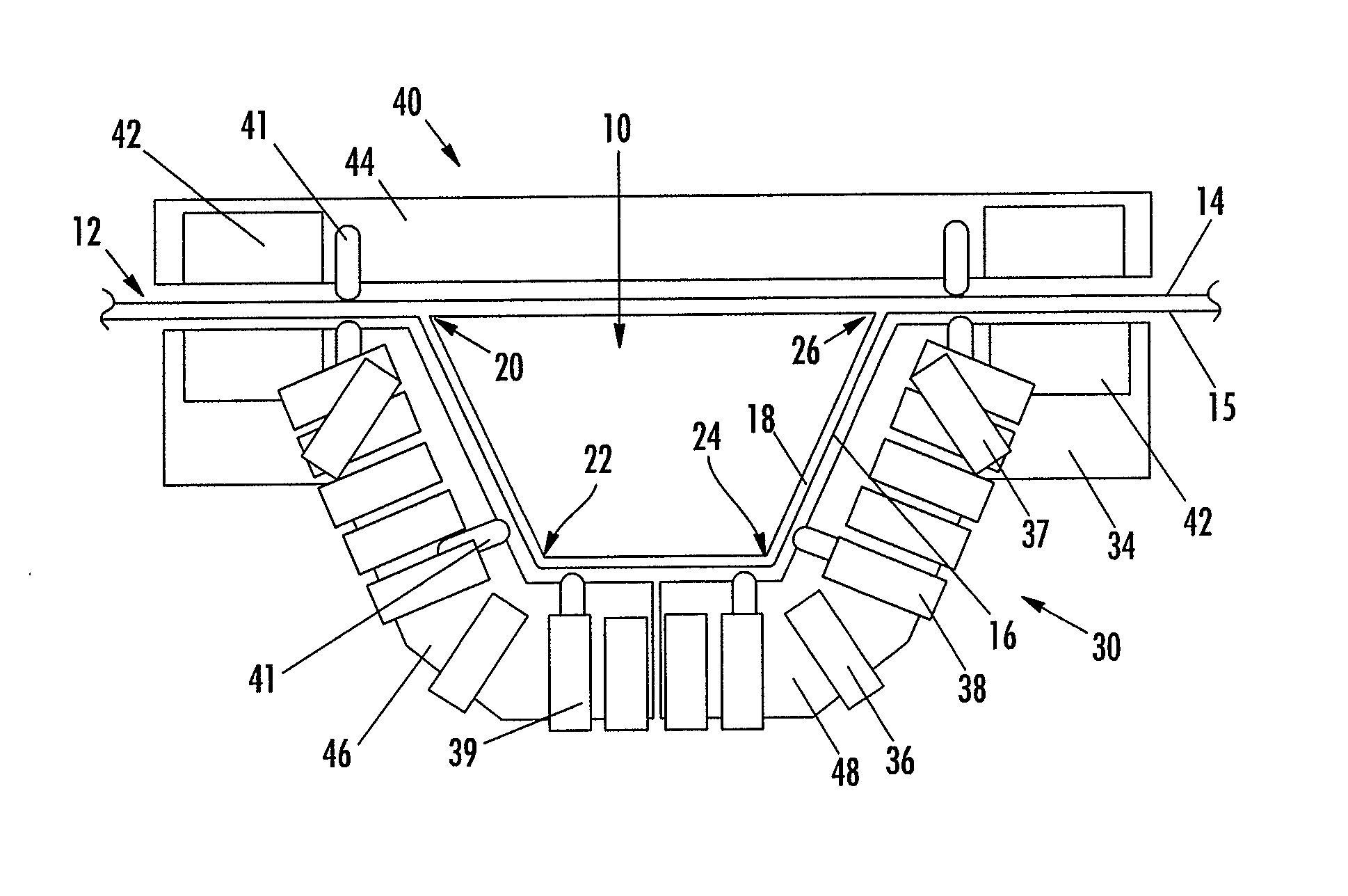
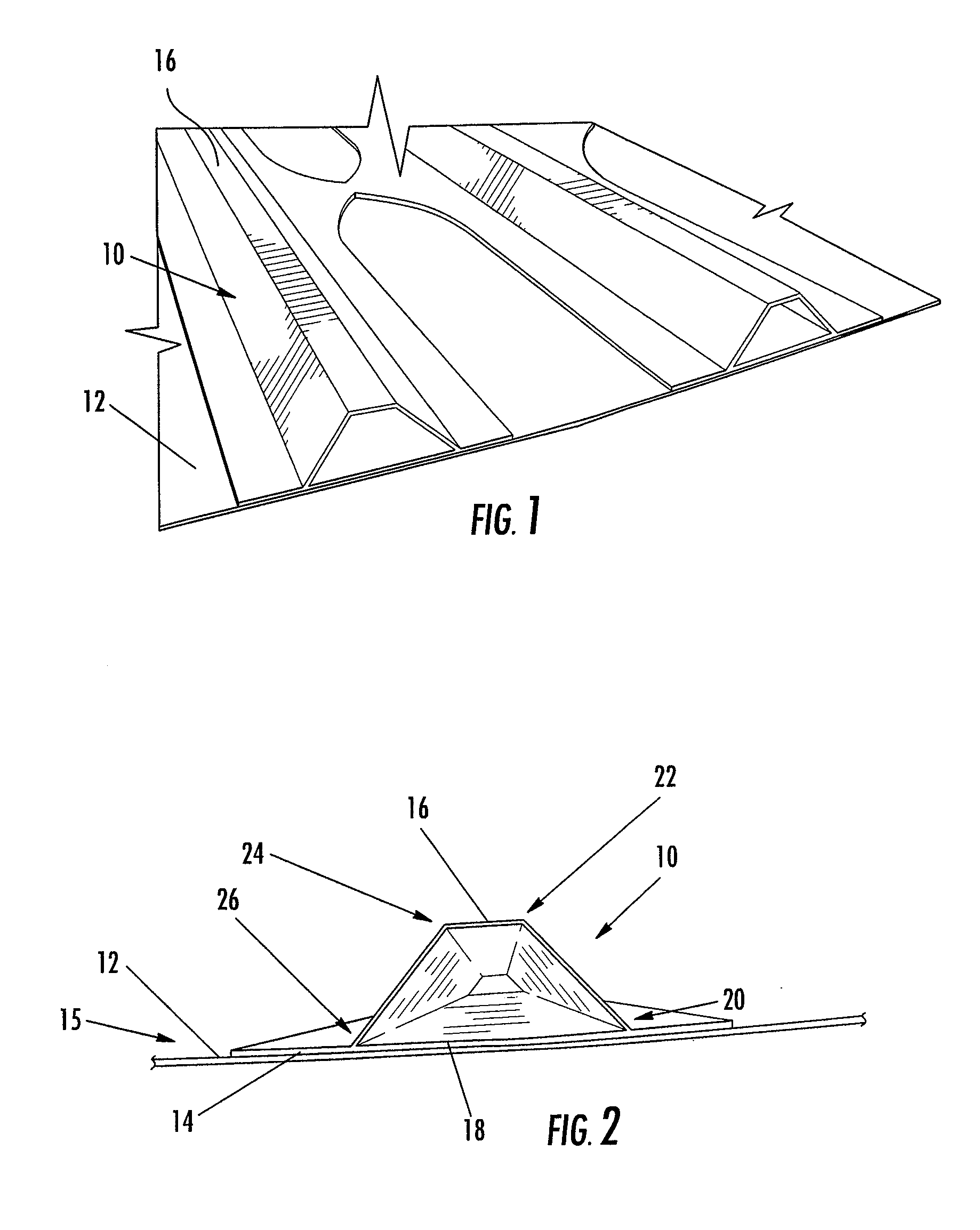
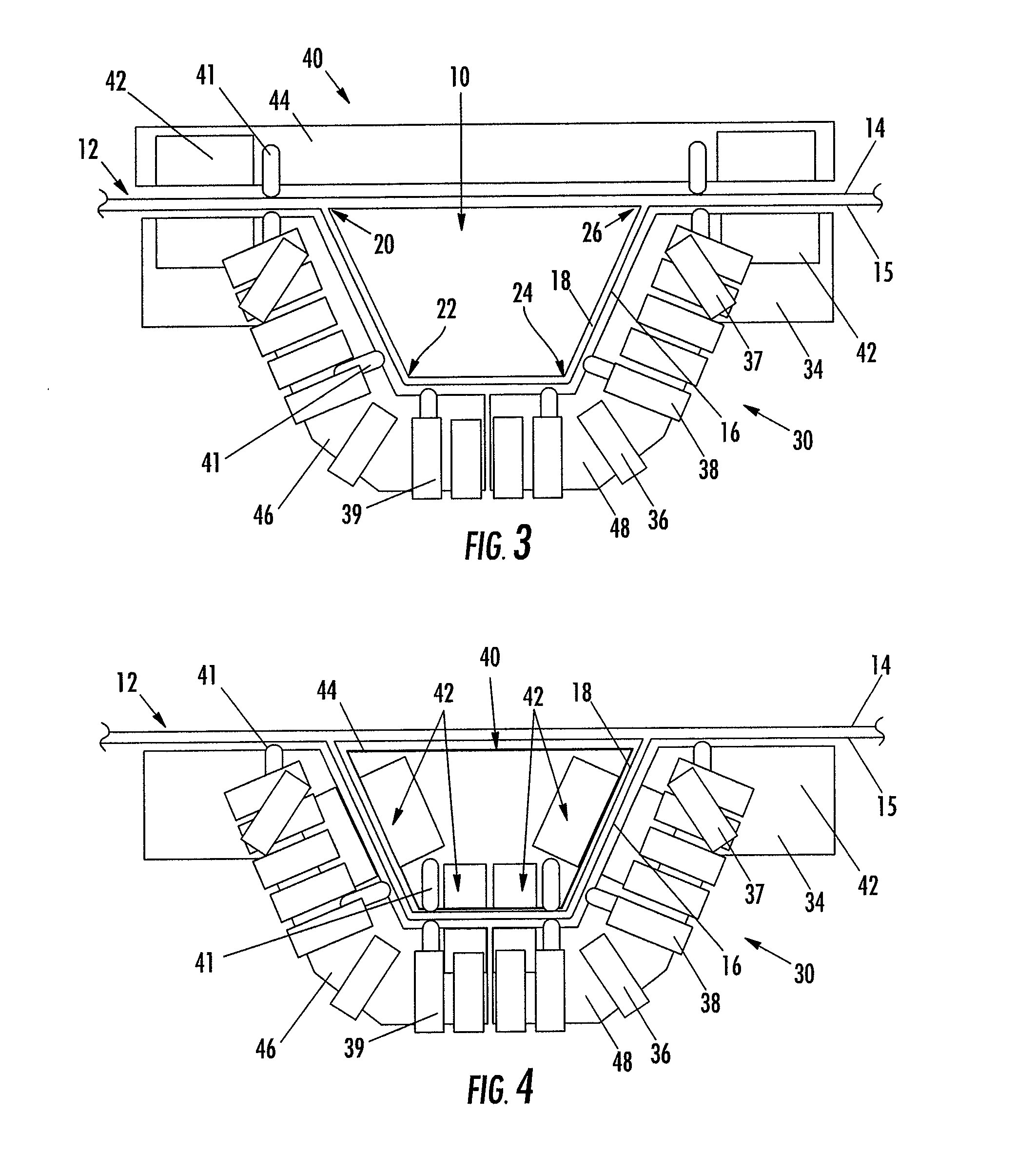
[0050] Embodiments of non-destructive stringer inspection apparatus and methods of the present invention are described with respect to hat stringers, especially composite hat stringers for an aircraft fuselage. However, the apparatus and methods may also be used for similar applications which require non-destructive inspection, including other composite structures with difficult-to-inspect geometric configurations and / or remote locations. Embodiments of hat stringer inspection apparatus and methods may include magnetically coupled probes as described in co-pending applications Ser. Nos. 10 / 943,088; 10 / 943,135; 10 / 7...


PUM


Abstract

A hat stringer inspection device permits continuous inspection of hat stringers as one or more probes are moved along the length of the hat stringer. Probes may be magnetically coupled to opposing surfaces of the structure, including, for example, where one of the probes is positioned inside the hat stringer and the probes are magnetically coupled across the surface of the hat stringer. The device may be autonomous with a feedback-controlled motor to drive the inspection device along the hat stringer. Magnetic coupling is also used to re-orient the position and / or alignment of the probes with respect to changes in the hat stringer or shapes, sizes, and configurations of hat stingers.

Description

CROSS-REFERENCE TO RELATED APPLICATIONS [0001] This application claims priority from and is a divisional of U.S. application Ser. No. 11 / 041,499, filed Jan. 24, 2005, the contents of which is hereby incorporated by reference herein in its entirety. The contents of U.S. Pat. No. 6,722,202 and co-pending application Ser. No. 10 / 752,890, entitled “Non-Destructive Inspection Device for Inspection Limited-Access Features of a Structure,” filed Jan. 7, 2004; application Ser. No. 10 / 943,135 entitled “Magnetically Attracted Inspecting Apparatus and Method Using a Fluid Bearing,” filed Sep. 16, 2004; application Ser. No. 10 / 943,088, entitled “Magnetically Attracted Inspecting Apparatus and Method Using a Ball Bearing,” filed Sep. 16, 2004; and application Ser. No. 10 / 943,170, entitled “Alignment Compensator for Magnetically Attracted Inspecting Apparatus and Method,” filed Sep. 16, 2004, are hereby incorporated by reference herein in their entirety.FIELD OF THE INVENTION [0002] The present i...

Claims


Application Information

Patent Timeline
Patent Type & Authority Applications(United States)
IPC IPC(8): G01M19/00G01M99/00
CPCG01N29/225G01N29/265G01N2291/0231G01N2291/2694G01N2291/0422G01N2291/105G01N2291/0258
Inventor KENNEDY, JAMES C.SARR, DENNIS P.CHAPMAN, MICHAEL R.FOGARTY, MICHAEL D.FREET, MARTIN L.GEORGESON, GARY E.VONWAHLDE, RONALD E.
Owner THE BOEING CO
Why Eureka
Try Eureka