
Mobile device tracking

a mobile device and tracking technology, applied in the direction of instruments, sensing by electromagnetic radiation, using reradiation, etc., can solve the problems of difficult to achieve, unsuitable solution, reducing the accuracy of position measurement, etc., and achieve the effect of relatively flexible positioning of each targ

Inactive Publication Date: 2007-07-05
TOSHIBA GLOBAL COMMERCE SOLUTIONS HLDG
View PDF28 Cites 63 Cited by
  • Summary
  • Abstract
  • Description
  • Claims
  • Application Information

AI Technical Summary

Benefits of technology

[0014] It is an object of the present invention to provide a system suitable for use in determining the location of a shopping cart in a store in which the target used to determine cart location is passive, that is, it requires no external power. It is a further object of the invention to determine the location of a shopping cart in a store from detection of a single target and further in which location of each target is relatively flexible.
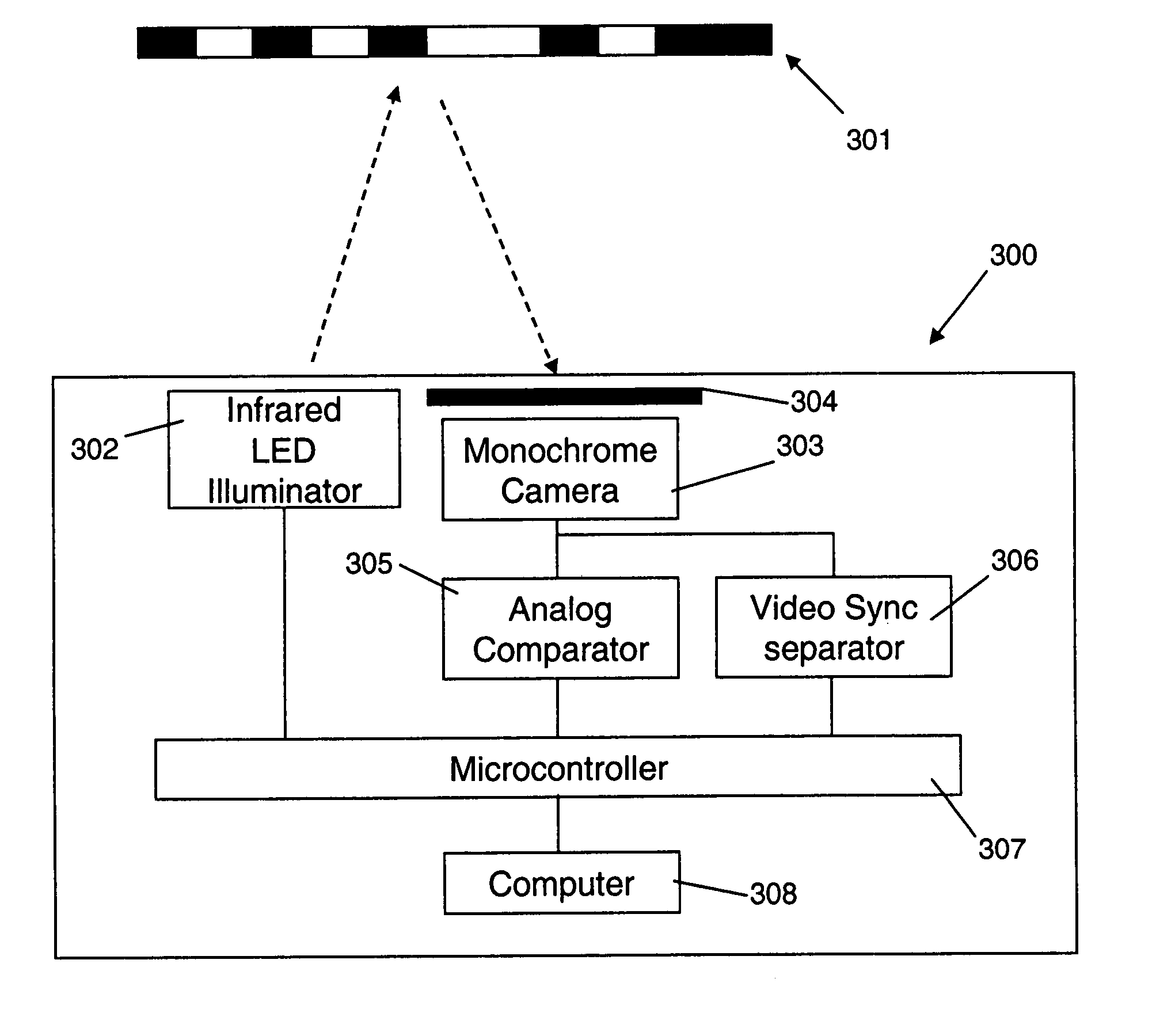
[0022] If a light source is used to illuminate the target optionally a first image and second images are obtained from a given location. The first image is obtained in the absence of the light source illuminating the target such that that target does not appear in the image, and the second image is obtained with the light source illuminating the target such that the target does appear in the image. The image of the target is then obtained by subtracting the first image from the second image. This reduces any background data in the image which is not part of the target making it easier to analyze.
[0030] If a comparator is used optionally at least one processor varies the predetermined brightness level to improve characteristics of the image which, for example, make it easier to obtain the identification data of the target.

Problems solved by technology

However, there are several problems with this method.
For example, the beacons require power and as a result it is necessary to either replace batteries in each beacon at regular time intervals or install an expensive wiring harness connected to an electricity supply.
Further store lighting and / or lighting ballasts can cause interference with the infra-red receiver on the cart, and also the granularity of the location depends on the distance between the beacons.
However this method also has known problems which include metal in the store environment causing reflections and multi-path, reducing accuracy of position measurement such that additional access points and directional antenna may have to be added to the store to provide sufficient spatial resolution and robustness.
However this solution is not suitable, for example, for determining cart location in a store because it requires a line of sight to at least 3 wall mounted reflectors which would be difficult to achieve for all possible cart locations in a large store.
However, this solution is not suitable, for example, for determining cart location in a store because it calculates only a distance from the reflectors and cannot distinguish one reflector from another.
As a result it is only possible to calculate location based on a known previous location which is not appropriate for a shopping cart.
However, this solution is also not suitable, for example, for determining cart location in a store because the scanning mechanism scans only selected areas and restricts the locations into which the retro-reflective elements must be placed.
However, guidance systems do not provide a solution suitable, for example, for determining cart location in a store in which a shopping car can be moved unpredictably around a store.
However because a customer with a shopping cart does not generally follow a prescribed path it is necessary to determine a location based on detection of a single target.
Accordingly none of the known art in related fields provides a solution to the problems associated with the current solutions to determining position of shopping cart.

Method used


Image

  • Mobile device tracking
  • Mobile device tracking
  • Mobile device tracking

Examples


Embodiment Construction

[0047] In the following description of the exemplary embodiment, reference is made to the accompanying drawings which form a part hereof, and in which is shown by way of illustration the specific embodiment in which the invention may be practiced. It is to be understood that other embodiments may be utilized as structural changes may be made without departing from the scope of the present invention.

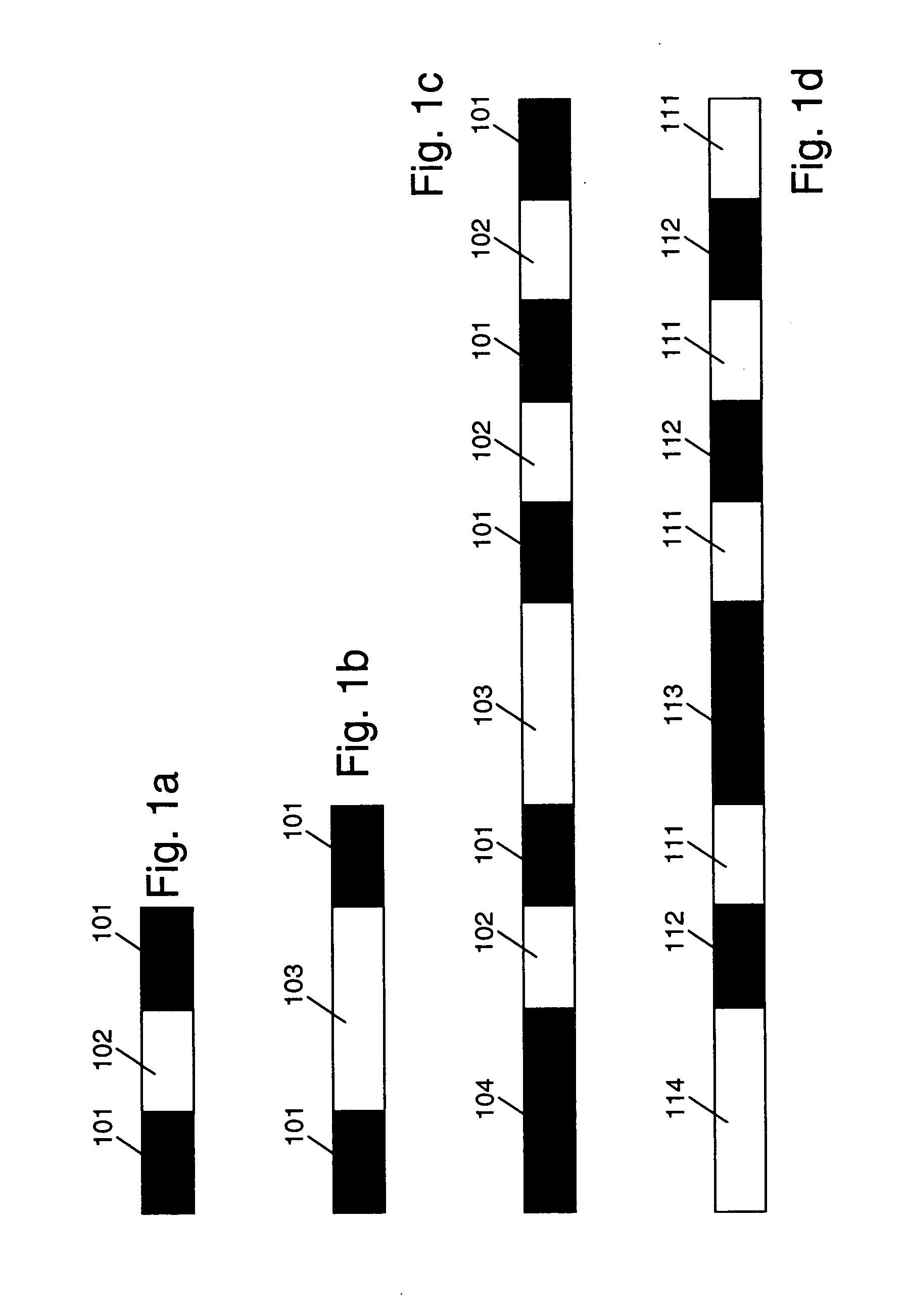
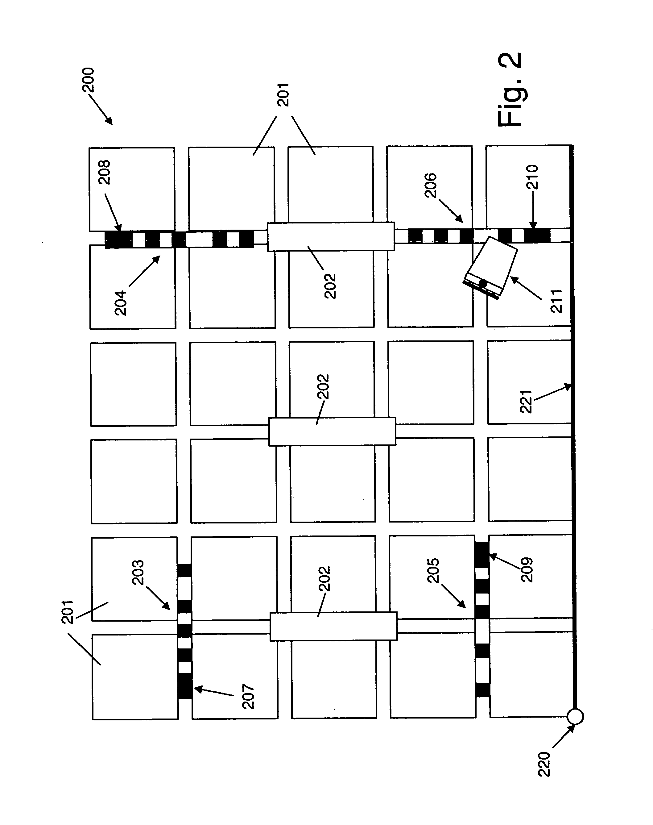
[0048] In the preferred embodiment of the present invention, the location of a shopping cart in a store is determined using retro-reflective barcode targets which are affixed to the ceiling of the store. An image of a barcode target is obtained using a camera mounted on the shopping cart such that a position in the image represents the cart location. The image is then analyzed to read the barcode and determine image positional data and image orientation data. The image positional data comprises “Cart / Barcode Image Polar Coordinates” which are the polar coordinates (in the image) of the c...


PUM


Abstract

The present invention provides a method, apparatus, and computer program product for obtaining the location of, for example, a mobile device. An image of a target in a defined space is obtained, the target encoding data from which its location in the defined space may be determined. The position of a reference point in the image which represents the location of, for example, a mobile device, is determined relative to the target. The location of the mobile device in the defined paces is then determined by combining the location of the target in the defined space with an appropriately scaled version of the relative position of the reference point to the target in the image.

Description

BACKGROUND TO THE INVENTION [0001] 1. Field of the Invention [0002] The present invention relates to mobile device tracking and more particularly to determining the location of a mobile device using targets which encode information. [0003] 2. Background to the Invention [0004] A common scenario in which location of a mobile device is obtained for the purposes of tracking is in a modem store where the mobile device which is tracked is a shopping cart. A cart may be tracked for a variety of reasons, for example, to obtain knowledge of the flow of customers through a store to use when arranging products in the store to avoid bottlenecks and ensure maximum exposure of specific products selected for promotion. For example, knowledge of the current location of a cart is used to provide information to the customer using the cart, which is pertinent to that location in the store, such information being provided to a display device associated with a shopping cart. [0005] One known method of ...

Claims


Application Information

Patent Timeline
Patent Type & Authority Applications(United States)
IPC IPC(8): G06K7/10
CPCG01S17/48G01S17/74G05D1/0244G05D1/0246G05D2201/0216G05D1/0242
Inventor CATO, ROBERT THOMASZIMMERMAN, THOMAS GUTHRIE
Owner TOSHIBA GLOBAL COMMERCE SOLUTIONS HLDG
Learn More