Organic light-emitting diode (OLED) display and data driver output stage thereof

a technology of light-emitting diodes and data drivers, applied in the field of output stage circuits of data drivers for oled displays, can solve the problems of large circuit area and increase cos

Inactive Publication Date: 2007-07-05
HIMAX TECH LTD
View PDF10 Cites 5 Cited by
  • Summary
  • Abstract
  • Description
  • Claims
  • Application Information

AI Technical Summary

Problems solved by technology

However, a wide power line consumes a large circuit area, which increases the cost.

Method used


Image

  • Organic light-emitting diode (OLED) display and data driver output stage thereof
  • Organic light-emitting diode (OLED) display and data driver output stage thereof
  • Organic light-emitting diode (OLED) display and data driver output stage thereof

Examples


Embodiment Construction

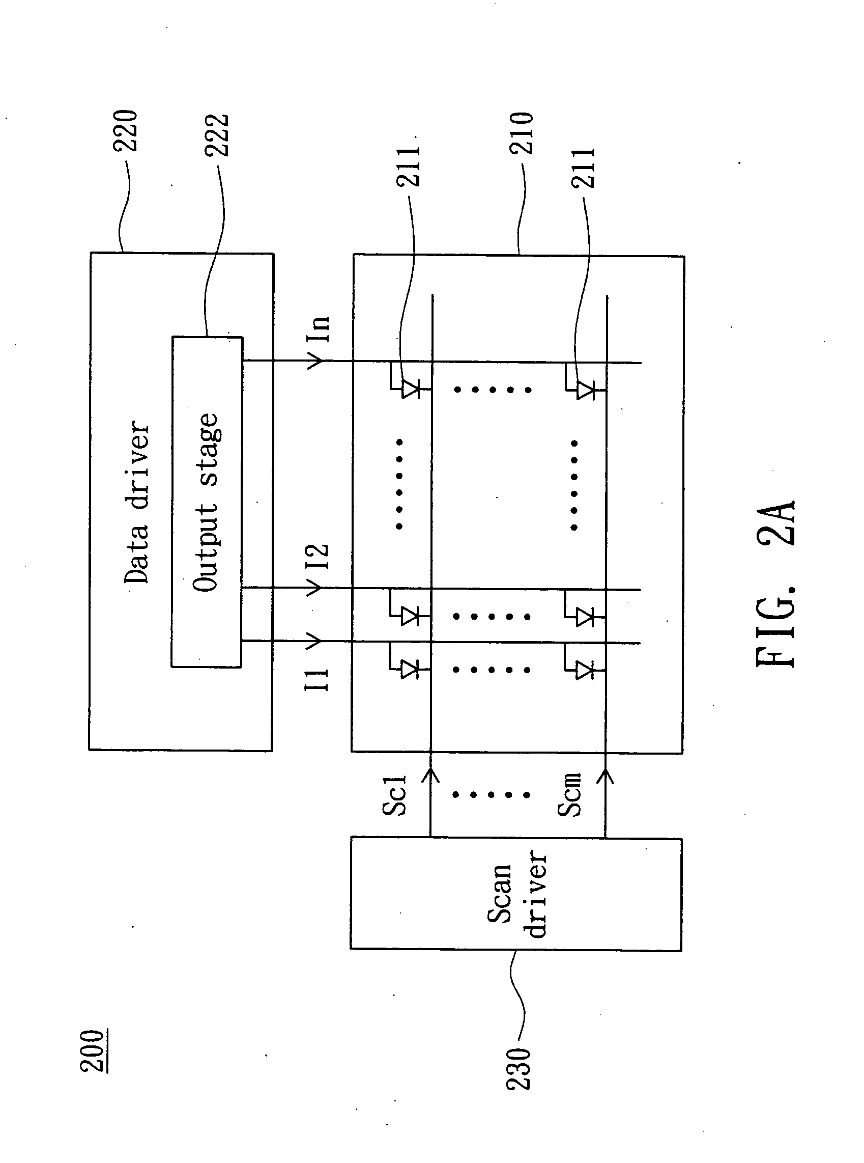
[0015]FIG. 2A shows an OLED display 200 according to a preferred embodiment of the invention. The OLED display 200 may be a passive matrix OLED (hereinafter referred to as PMOLED) display or a current mode active matrix OLED (hereinafter referred to as AMOLED) display, and includes an OLED display panel 210, a data driver 220 and a scan driver 230. The panel 210 includes m×n pixels 211, wherein m and n are positive integers. The data driver 220 outputs n data currents I1 to In to the n columns of the pixels 211 through an output stage circuit 222. The m rows of the pixels 211 are sequentially enabled by the scan signals Sc1 to Scm to be driven by the data currents so that frames of a video clip are displayed.

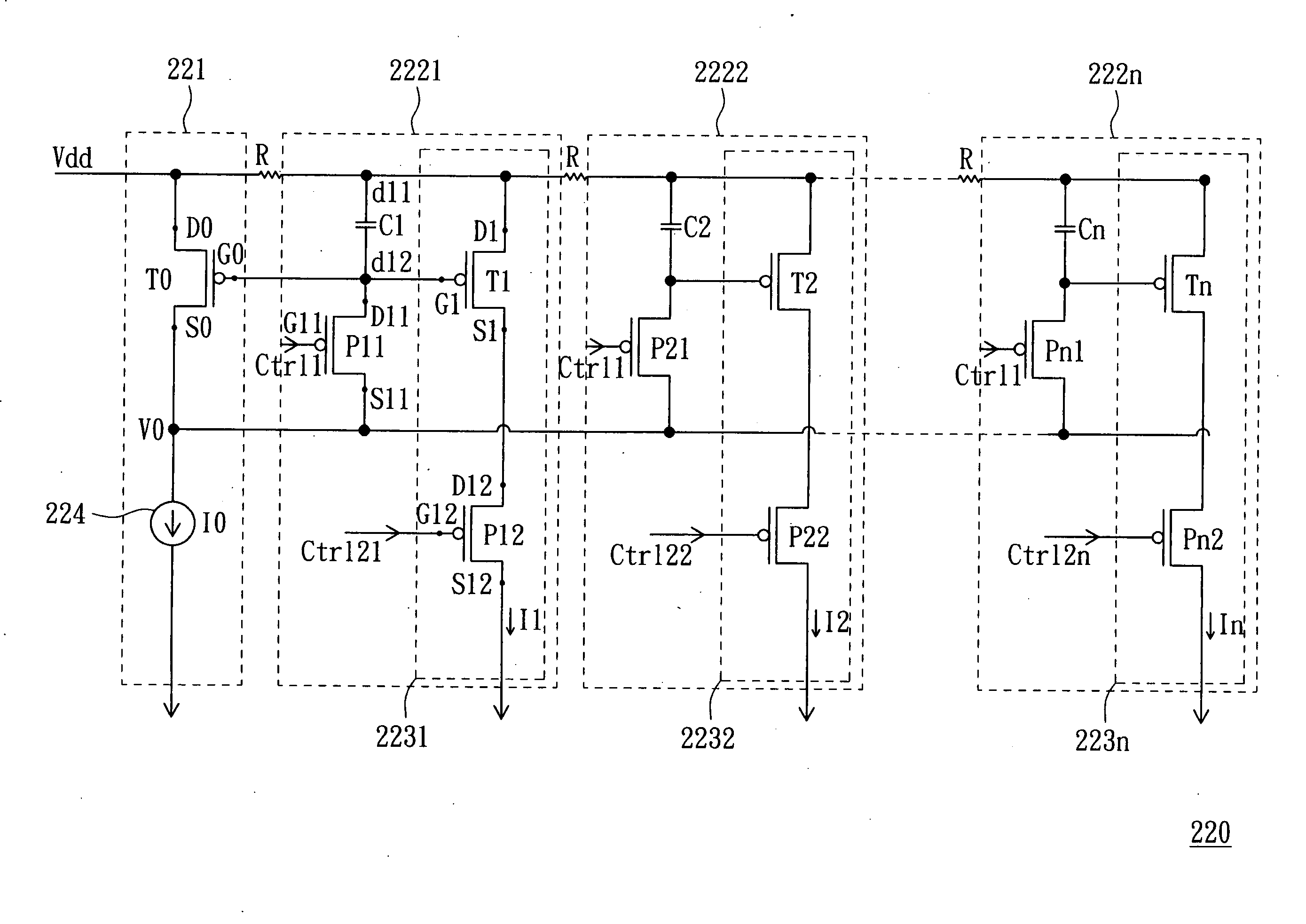
[0016]FIG. 2B shows the output stage circuit 222 of FIG. 2A. The output stage circuit 222 is substantially a modified current mirror which provides data currents I1˜In by mirroring a reference current I0 from the circuit 221 onto output channels of the circuits 2221 to 222n. Th...


PUM


Abstract

An output stage circuit of a data driver for an display is provided. The circuit includes a current mirror having a first transistor and a current source on a reference current path, having a second transistor on an output current path, wherein the reference and output current paths are commonly coupled to a power line, a capacitor having a first end coupled to the power line and a second end coupled to a gate of the second transistor, a first switch cutting off the output current path during a first period, and a second switch coupling the second end of the capacitor to the current source during the first period.

Description

[0001] This application claims the benefit of Taiwan application Serial No. 95100237, filed Jan. 3, 2006, the subject matter of which is incorporated herein by reference. BACKGROUND OF THE INVENTION [0002] 1. Field of the Invention [0003] The invention relates to an OLED display and, and more particularly to an output stage circuit of a data driver for the OLED display. [0004] 2. Description of the Related Art [0005]FIG. 1 shows a conventional output stage circuit 100 of a data driver for the OLED display. The circuit 100 is substantially a current mirror which provides data currents I1˜n by mirroring a reference current I from the circuit 110 onto output channels of the circuits 120. Due to a large number of the output channels, the supply voltage Vdd is transmitted through a relatively long power line 130 having parasitic resistors R. The long power line 130 results in drops of the supply voltages actually received by the circuits 120 and causes non-uniformity of the data currents...

Claims


Application Information

Patent Timeline
Patent Type & Authority Applications(United States)
IPC IPC(8): G09G3/30
CPCG09G3/2022G09G3/3283G09G2330/02G09G2320/0223G09G2320/0233G09G2310/0251
Inventor CHIOU, YU-WEN
Owner HIMAX TECH LTD
Why Eureka
Try Eureka