Control circuit for current detection

a control circuit and current detection technology, applied in the field of control circuits, can solve problems such as reducing the working efficiency of pse, and achieve the effect of avoiding the generation of incorrect signals

Inactive Publication Date: 2011-05-19
ANALOGTEK CORP
View PDF6 Cites 3 Cited by
  • Summary
  • Abstract
  • Description
  • Claims
  • Application Information

AI Technical Summary

Benefits of technology

Another objective of the present invention is to provide a control circuit for current detection, which comprises a capacitor and an operational amplifier disposed between a positive voltage terminal thereof and a negative voltage terminal thereof. When power noise is generated at the positive voltage terminal, the capacitor transmits the power noise from the positive voltage terminal to the negative voltage terminal by utilizing the virtual short characteristic for a position between a positive input terminal and a negative input terminal of the operational amplifier whereby a voltage drop of the power noise between the positive voltage terminal and the negative voltage terminal is eliminated. Besides, the capacitor can avoid generation of incorrect signals.

Problems solved by technology

However, the power consumption of the external power resistor reduces the working efficiency of PSE.

Method used


Image

  • Control circuit for current detection
  • Control circuit for current detection
  • Control circuit for current detection

Examples


Embodiment Construction

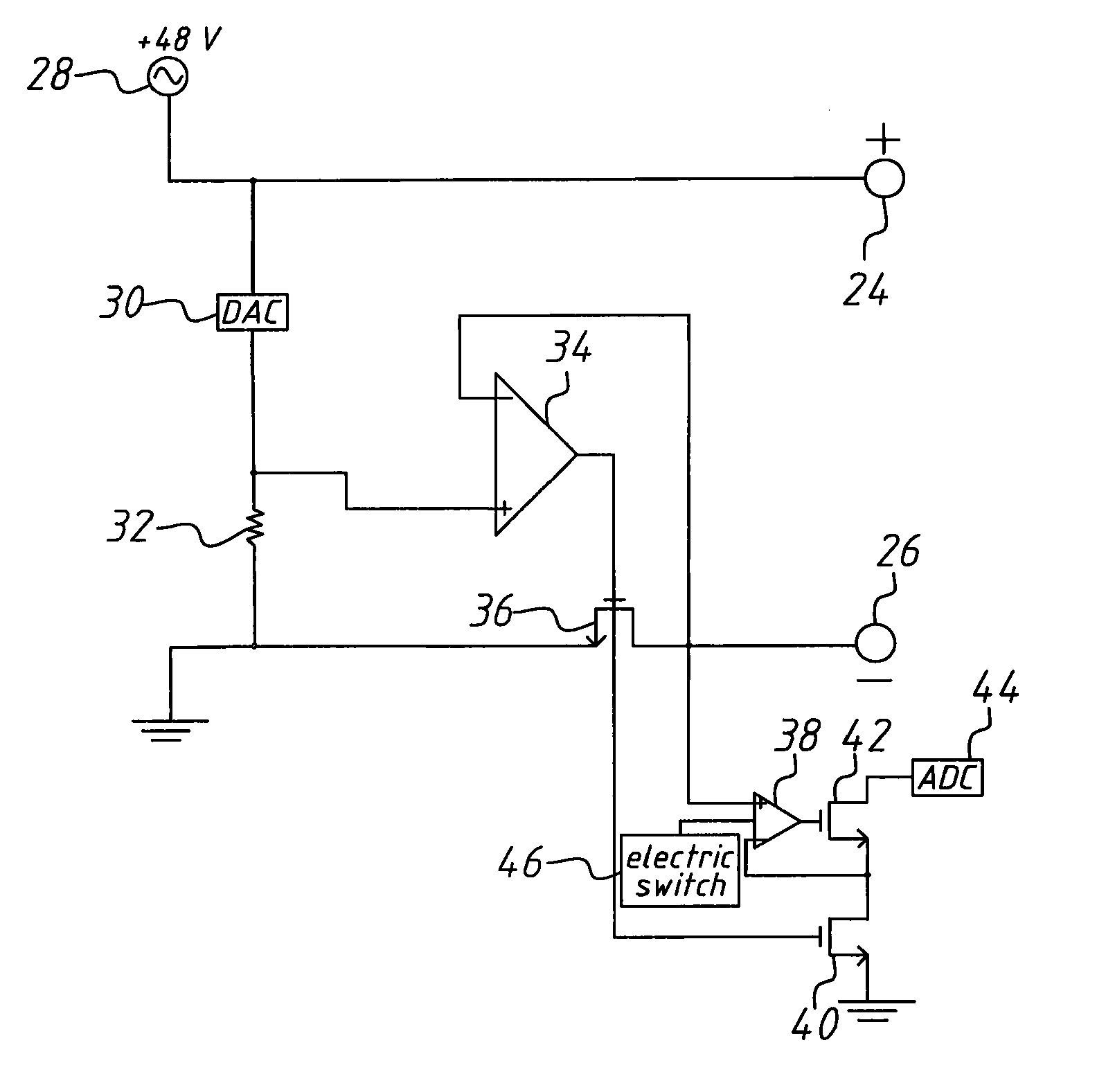
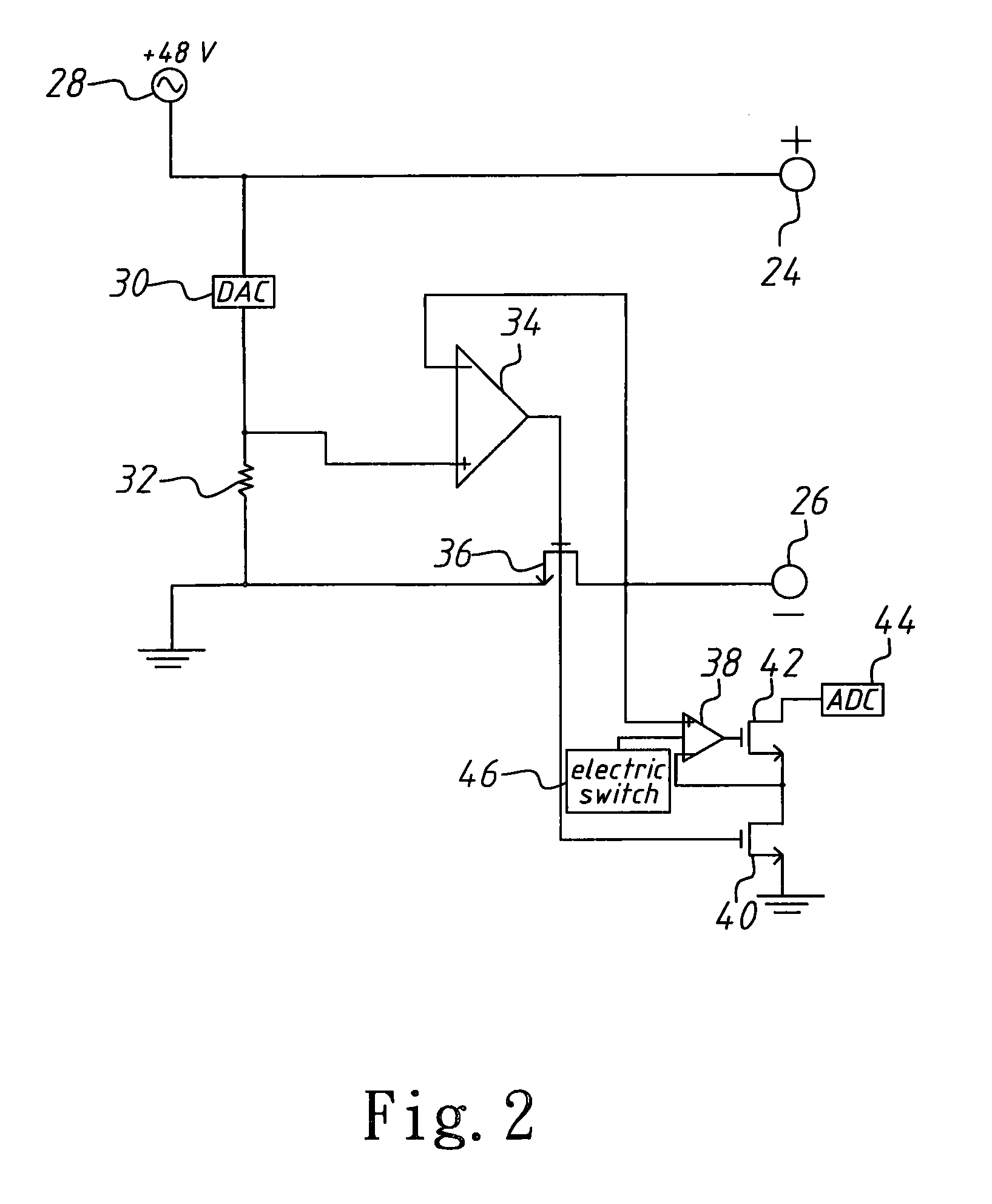
The present invention is applied to Power over Ethernet (PoE). Below is a description of a first embodiment. Refer to FIG. 2. The control circuit for current detection of the present invention which is installed inside Power Sourcing Equipment (PSE) of PoE, is coupled to Power Device (PD) to detect an output current output from PSE to PD.

The control circuit for current detection comprises a positive voltage terminal 24 and a negative voltage terminal 26. The positive voltage terminal 24 and the negative voltage terminal 26 are respectively coupled to PD. The positive voltage terminal 24 coupled to a voltage source 28 providing a direct-current (DC) input voltage of 48 V is used to output the output current. The voltage source 28 is coupled to a current mode digital-to-analog converter (DAC) 30. The current mode digital-to-analog converter (DAC) 30 is coupled to a side of a resistor 32. The resistor 32 with another side thereof is separately coupled to the source of at least one firs...


PUM


Abstract

A control circuit for current detection is disclosed. The control circuit outputting an output current to a power device comprises at least one first Field Effect Transistor (FET) coupled to the positive input terminal of an operational amplifier. The first FET is coupled to the power device through two voltage terminals, wherein the output current is passed through the first FET. The control circuit further comprises at least one second FET coupled to the first FET and the negative input terminal of the first operational amplifier, utilizing the virtual-short characteristic of the first operational amplifier to form a current mirror with the first FET, and copying the output current to generate a copy current by a scale whereby the output current is detected by the copy current. The invention detects the output current without consuming additional power so as to measure the power consumption for the power device.

Description

BACKGROUND OF THE INVENTION1. Field of the InventionThe present invention relates to a control circuit, particularly to a control circuit for current detection.2. Description of the Related ArtPower over Ethernet (PoE) is a system, which obtains power through cables. In other words, when users' internet equipments are provided with PoE, the internet equipments are connected to the cables to work normally without coupling to a plug. The above-mentioned function of PoE is very convenient.As shown in FIG. 1, in general, PoE 10 comprises Power Sourcing Equipment (PSE) 12 and Power Device (PD) 14. PSE 12 and PD 14 are both used together otherwise PoE 10 won't function properly. PSE 12 has to detect its output current to tell the upper system the power consumption for PD 14 and prevent short-circuiting. Therefore, in the traditional technology, a control circuit 16 turns on a transistor 18 such that current flows to the PD 14 through the transistor 18. A power resistor 20, connected with ...

Claims


Application Information

Patent Timeline
Patent Type & Authority Applications(United States)
IPC IPC(8): G01R19/00
CPCG01R19/0092
Inventor LIN, YUH-MINSHIH, HO-YI
Owner ANALOGTEK CORP
Why Eureka
Try Eureka