LCD Driver

Inactive Publication Date: 2007-07-05
JPS GRP HLDG
View PDF6 Cites 0 Cited by
  • Summary
  • Abstract
  • Description
  • Claims
  • Application Information

AI Technical Summary

Benefits of technology

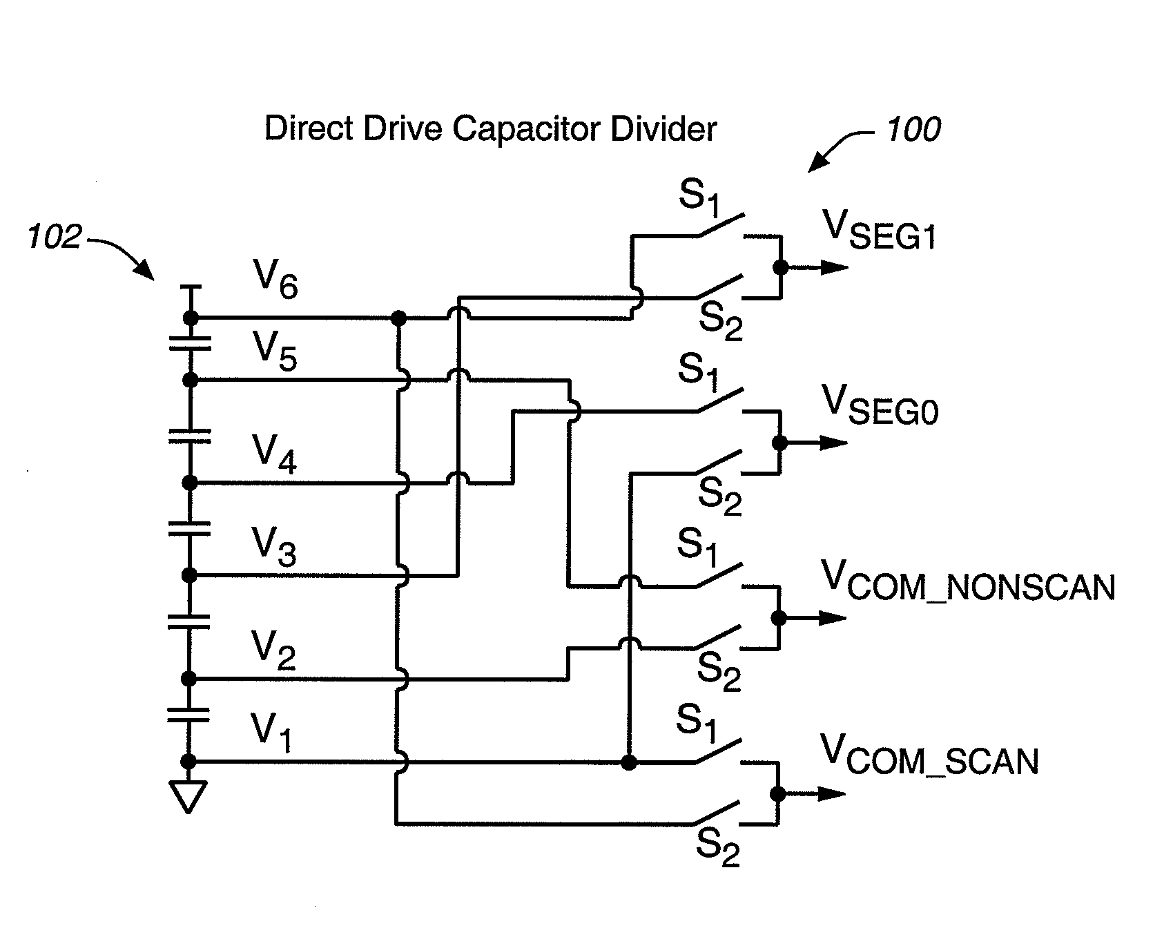
[0011] This invention is based on the recognition that power consumption by the LCD driver can be reduced if a capacitor divider comprising a plurality of capacitors is used to provide one or more voltage level(s) and power for driving the LCD. In one embodiment, the capacitor divider comprises a plurality of capacitors that are electrically connected. The capacitor divider may be employed to provide IAPT as well as APT voltage levels or other driving waveform levels. In one embodiment, the control device such as one comprising one or more switches may be employed to connect the divider to row and column electrodes of an LCD to provide suitable voltage levels for driving the electrodes.

Problems solved by technology

One drawback of such a circuit is that a constant current flows through the power supply and causes constant power dissipation.
One of the most frequently heard complaints from users of portable devices, such as portable computers, cellular phones and personal digital assistants is that these devices consume too much power so that one has to constantly charge batteries, which is inconvenient.
But this has a negative effect of increasing chip die size.

Method used


Image

  • LCD Driver
  • LCD Driver
  • LCD Driver

Examples


Embodiment Construction

[0025] The ratio of VLCD over VB in FIG. 2c is defined as a parameter called bias ratio. Instead of a resistor ladder as used conventionally, a capacitor divider circuit 10 can be employed to generate the bias ratio and to provide the electrical potentials VLCD and VB of FIG. 2c as shown in FIG. 3. The bias ratio BR is BR=C2+C1C1Eg. ⁢2

where C1 and C2 are values of the top capacitor 12 and bottom capacitor 14 in FIG. 3.

[0026] Since no static current is required to drive the capacitor divider 10, power is saved through this approach.

[0027] One drawback of this approach is that the node A between two capacitors is a floating node (i.e. at a floating electrical potential). Its initial voltage is undetermined. Also over long period of time, the voltage may tend to drift because of capacitor leakage current. These two factors will affect the voltage value at node A.

[0028] These two problems are solved by a periodic refreshing circuitry in the capacitor divider 20 as shown in FIG. 4. ...


PUM


Abstract

A capacitor divider comprising a plurality of capacitors is used for driving liquid crystal displays. The use of capacitor dividers reduces power consumption, which would be desirable for portable devices. Power consumption is reduced in some embodiments where no static current would flow in the divider.

Description

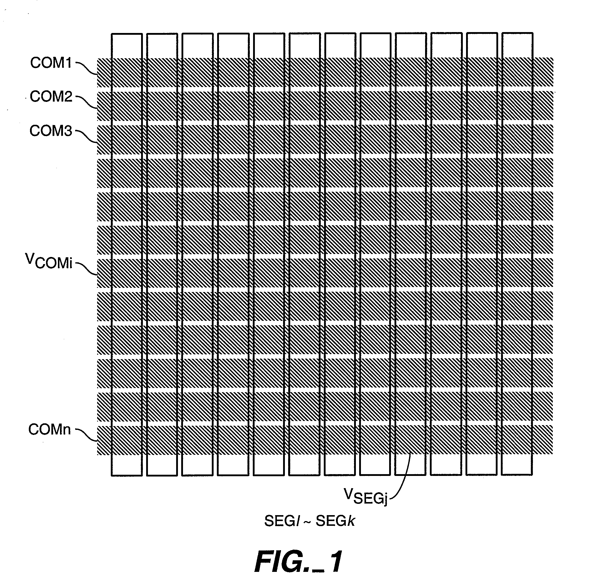
CROSS REFERENCE TO RELATED APPLICATIONS [0001] This application is a divisional of application Ser. No. 10 / 665,810 filed on Sep. 19, 2003, which claims the benefit of Provisional Application No. 60 / 416,855 filed Oct. 8, 2002 which applications are incorporated herein by reference in their entirety.BACKGROUND OF THE INVENTION [0002] This invention relates in general to liquid crystal displays (LCDs) and, in particular, to an LCD driver. [0003]FIG. 1 is a schematic view of a LCD panel and its n row electrodes labeled COM 1, . . . COM n in FIG. 1, and k column electrodes shown as vertical rectangles labeled SEG 1˜SEGk in FIG. 1. Not shown in FIG. 1 (to simplify the figure) is a layer of liquid crystal material between the row and column electrodes. When an appropriate voltage is applied across a particular row and a particular column electrode, a portion of the liquid crystal layer between the particular row and column electrodes where they overlap controls the light transmission or re...

Claims


Application Information

Patent Timeline
IPC IPC(8): G09G3/36
CPCG09G3/3696
Inventor XIAO, PETER H.LIANG, JEMM Y.
Owner JPS GRP HLDG
Why Eureka
Try Eureka