Optical pickup apparatus

Inactive Publication Date: 2007-07-05
LG ELECTRONICS INC
View PDF10 Cites 0 Cited by
  • Summary
  • Abstract
  • Description
  • Claims
  • Application Information

AI Technical Summary

Benefits of technology

[0012] Accordingly, the present invention is directed to an optical pickup apparatus that subst

Problems solved by technology

However, since two sub-beams need to be separated by ½ track pitch with respect to a main beam in the DPP method, it cannot be applied to an optical recording medium having a different track pitch.

Method used


Image

  • Optical pickup apparatus
  • Optical pickup apparatus
  • Optical pickup apparatus

Examples


Embodiment Construction

[0027] Reference will now be made in detail to the preferred embodiments of the present invention, examples of which are illustrated in the accompanying drawings.

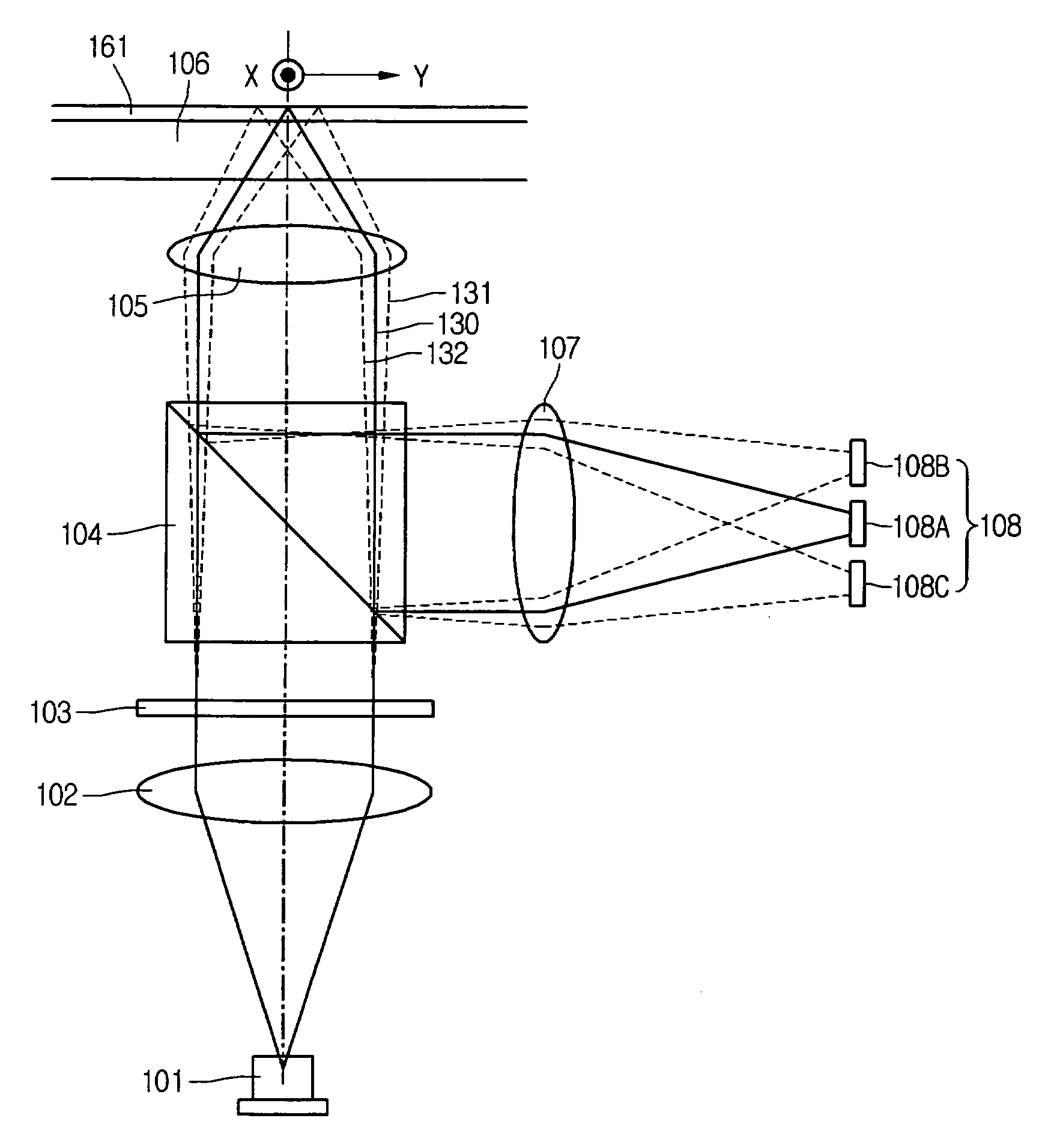
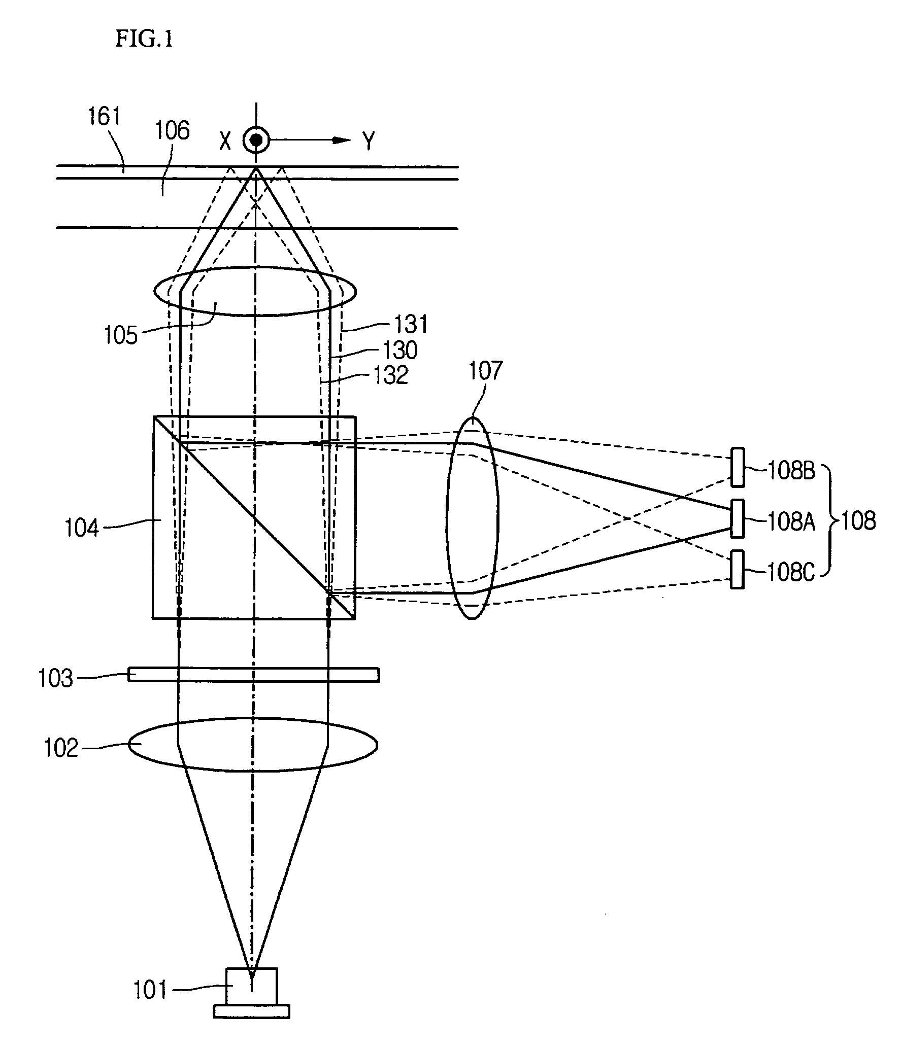
[0028]FIG. 1 is a schematic view illustrating a construction of an optical system of an optical pickup according to an embodiment of the present invention. Such an optical pickup can be used in any recording and / or reproducing device according to the present invention.

[0029] Referring to FIG. 1, light emitted from a laser diode 101 is changed into parallel light at a collimator 102, and is divided into a main beam 130 and two sub-beams 131 and 132 by a grating 103.

[0030] After passing through a beam splitter 104, the three beams 130, 131, and 132 are condensed onto a track 161 of an optical recording medium 106 by an objective lens 105. The three beams 130, 131, and 132 reflected by the recording medium 106 pass through the objective lens 105, and are reflected by the beam splitter 104 and guided to a light detector 108 ...


PUM


Abstract

An optical pickup apparatus according to an embodiment includes a semiconductor laser, an objective lens, a grating, and a light detecting device. The grating is installed between the semiconductor laser and the objective lens to divide the light beam emitted from the semiconductor laser into three beams or more including a main beam and a sub-beam. The light detecting device receives the divided light reflected by the optical recording medium. The grating includes a first diffraction grating and a second diffraction grating. The first diffraction grating has patterns formed for dividing a sub-beam with respect to a first optical recording medium having a first track pitch, and second diffraction grating has patterns formed for dividing the sub-beam divided by the first diffraction grating into sub-beams with respect to a second optical recording medium having a second track pitch.

Description

[0001] This application claims the priority benefit of Korean Patent Application No. 10-2005-0132814, filed on Dec. 29, 2005, which is hereby incorporated by reference for all purposes as if fully set forth herein. BACKGROUND OF THE INVENTION [0002] 1. Field of the Invention [0003] The present invention relates to an optical pickup apparatus. [0004] 2. Description of the Related Art [0005] Since an optical recording medium can record a high capacity data signal in high density, it is widely applied in fields requiring recording and reproduction of data. [0006] Recently, as data such as a moving image requiring a high capacity recording medium increases, a study is in progress to manufacture a high capacity optical recording medium through reduction of a recording pit and a track pitch. [0007] Generally, it is desirable to accurately track a light beam on a track of an optical recording medium in order to reproduce a data signal recorded by a micron unit. [0008] Various methods are k...

Claims


Application Information

Patent Timeline
IPC IPC(8): G11B7/00G11B7/135
CPCG11B7/0903G11B2007/0006G11B7/1353
Inventor KANG, DO WON
Owner LG ELECTRONICS INC
Why Eureka
Try Eureka