Low Latency Digital Audio over Packet Switched Networks

a packet switched network and low latency technology, applied in the field of digital audio, can solve the problems of cobranet not efficiently using switched ethernet and data is naturally burs

Inactive Publication Date: 2007-07-05
TLS CORP
View PDF14 Cites 33 Cited by
  • Summary
  • Abstract
  • Description
  • Claims
  • Application Information

AI Technical Summary

Problems solved by technology

That is because data is naturally bursty.
This works, but is inefficient because the line is held open and null data is being sent between the bursts of data that matter.
However, CobraNet does not use switched Ethernet efficiently when audio and data share a link.

Method used


Image

  • Low Latency Digital Audio over Packet Switched Networks
  • Low Latency Digital Audio over Packet Switched Networks
  • Low Latency Digital Audio over Packet Switched Networks

Examples


Embodiment Construction

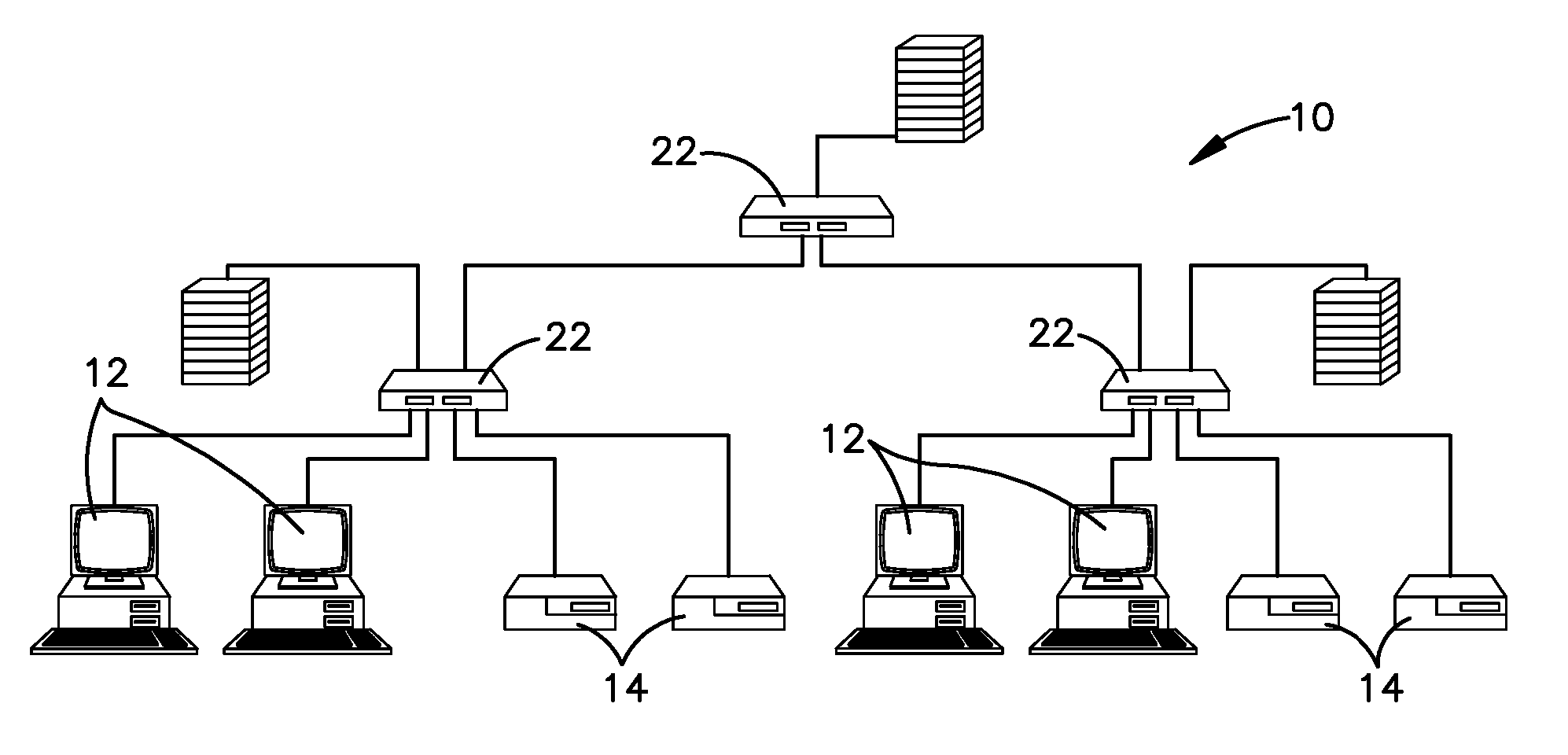
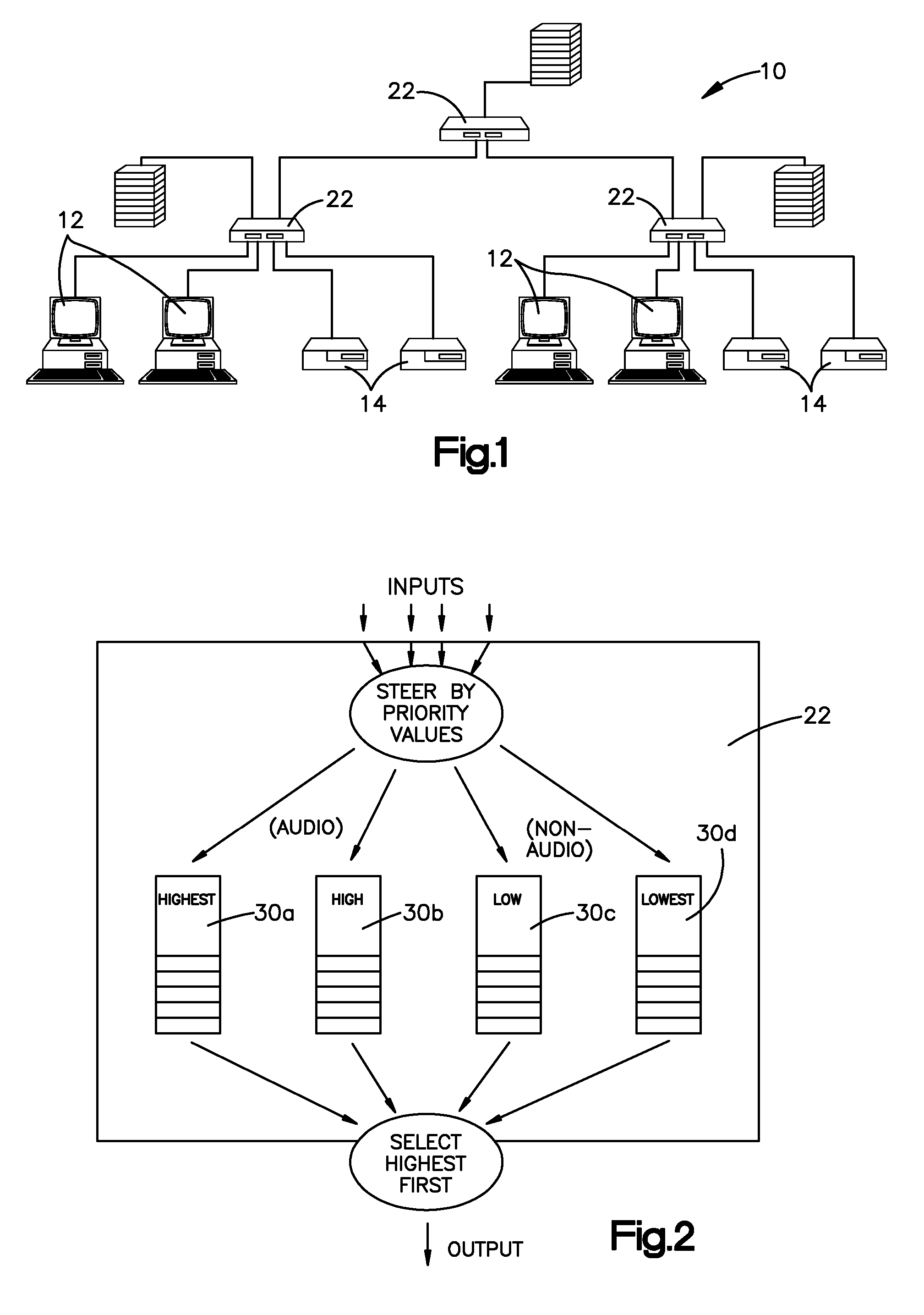
[0036]FIG. 1 is schematic depiction of a general architecture design of a network 10 that is used at a facility having multiple computers 12 and other audio equipment 14. The network 10 uses a switched Ethernet network for delivering both audio and data to any node (such as one of the computers 12) on the network. A node need not include an entire computer but instead may simply be circuitry that includes a network interface circuit and an audio jack for plugging in a speaker, set of headphones, microphone or amplifier. FIG. 9 is a functional block diagram of a typical node on the network 10.

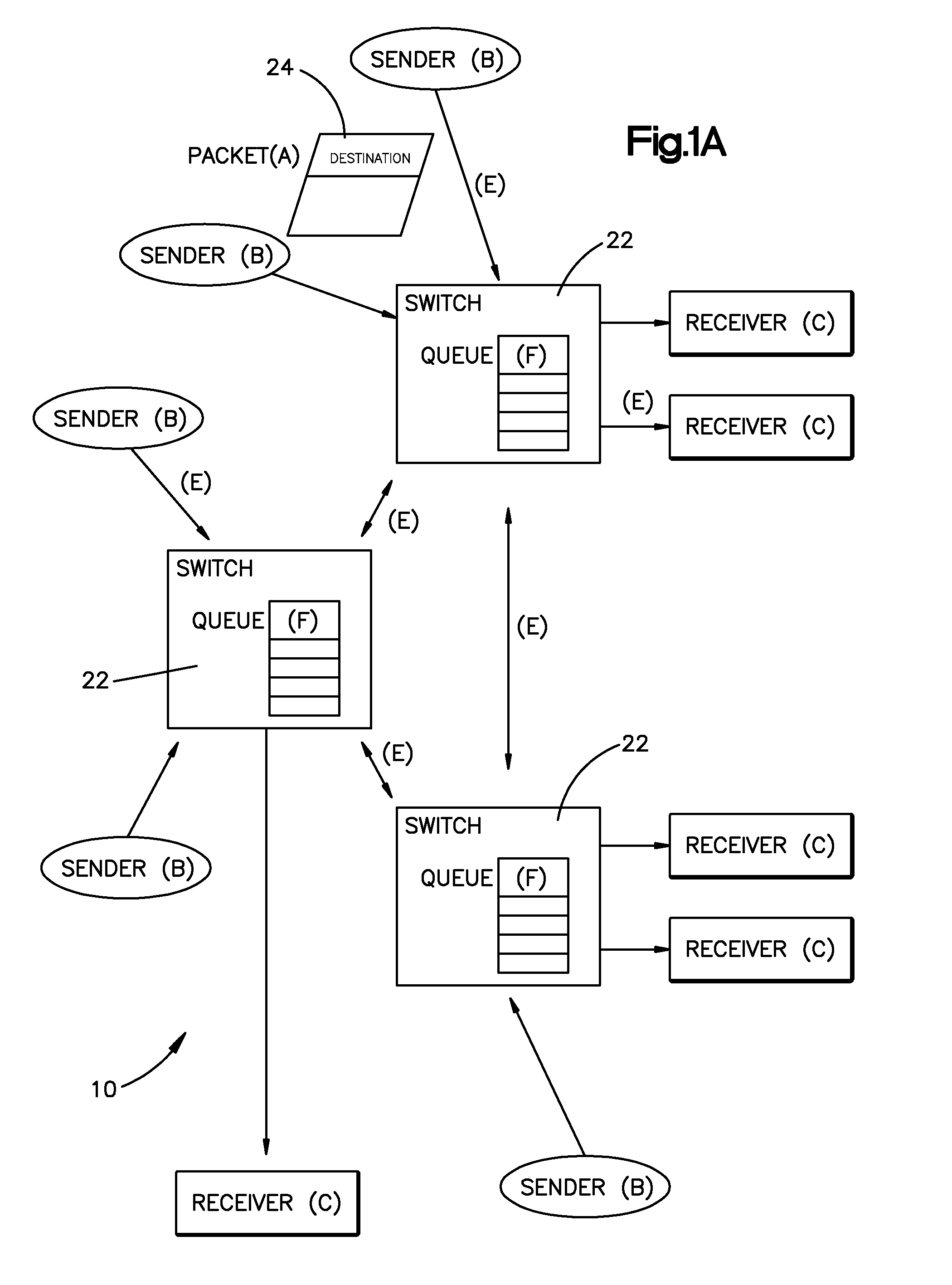
[0037] Key to implementing the network shown in FIG. 1 is the use of priority tagging and the action of Ethernet switches 22 (three of which are depicted in FIG. 1) that deliver higher priority packets first before any waiting lower priority (non-audio) packets. Another design point is for each channel receiver (non-switch node) to have just enough audio data buffer to allow one full size (non-...


PUM


Abstract

Method and Apparatus for delivering audio signals from a source node to a destination node on a network. The apparatus uses a number of switches that transmit prioritized data on a packet network. The switches are coupled to a number of send / receive nodes for sending and receiving digital audio signals on the data network. The audio packet size and the receive buffers are sized to store a minimum possible number of audio samples to minimize latency in processing audio signals arriving at said receive node, but still ensure audio delivery without interruption due to packet data network delay. An additional feature of the invention is recovery of clock synchronization over the same data network by novel arrangement of transmission of timing packets on the network. By sending a multiplicity of packets at irregular intervals a minimum network transit delay can be determined by each of the receive nodes which allows the receive nodes to filter out packet network transit delay error and maintain accurate local clocks.

Description

CROSS REFERENCE TO RELATED APPLICATIONS [0001] The present application claims priority from provisional application Ser. No. 60 / 433,922 filed Dec. 17, 2002.FIELD OF THE INVENTION [0002] The present invention concerns digital audio and more particularly a low latency means of transmitting digital audio signals over a network having multiple connections or nodes. BACKGROUND ART [0003] Computer networks are defined by their structure—bus, star, or some combination, and the organization of their bits—packets, continuous, or some combination. [0004] Computer networks are almost always packet-based. That is because data is naturally bursty. A lot of data flows when a user opens a web page, but while he or she is reading it there is no data moving. Packets also let a number of terminals share the same wire. [0005] In contrast, digital telephone networks are “circuit-switched”—a circuit is open for the duration of the connection. These two styles are good matches to the two data types, but ...

Claims


Application Information

Patent Timeline
Patent Type & Authority Applications(United States)
IPC IPC(8): H04L12/66H04L29/06
CPCH04J3/0632H04L65/80H04L12/66H04J3/0664
Inventor SHAY, GREGORY F.CHURCH, STEVEN GRAY
Owner TLS CORP
Why Eureka
Try Eureka