Fluid transfer controllers having a rotor assembly with multiple sets of rotor blades arranged in proximity and about the same hub component and further having barrier components configured to form passages for routing fluid through the multiple sets of rotor blades

a technology of fluid transfer controller and rotor blade, which is applied in the direction of liquid fuel engines, machines/engines, priming pumps, etc., can solve the problems of limited extent to which the orientation, size and speed of the rotor blade may be effectively manipulated to enhance the acceleration of fluid flow, and the difficulty of transporting fluid between controllers without significantly diminishing its velocity or pressur

Inactive Publication Date: 2007-07-05
MACRO MICRO DEVICES
View PDF18 Cites 27 Cited by
  • Summary
  • Abstract
  • Description
  • Claims
  • Application Information

AI Technical Summary

Benefits of technology

[0010] The problems outlined above may be in large part addressed by fluid transfer controlling equipment having a rotor assembly with multiple sets of rotor blades coupled to a common hub component and barrier components configured to form passages for routing fluid through the multiple sets of rotor blades. The

Problems solved by technology

By appropriately rotating the rotor, the blades of the rotor may accelerate the fluid, allowing the fluid to exit the rotor assembly with increased velocity and possibly increased pressure.
Unfortunately, however, the extent to which the orientation, size, and speed of the rotor blades may be effectively manipulated to enhance fluid flow acceleration is limited.
In particular, transporting a fluid between controllers without significantly diminishing its velocity or pressure is difficult and, thus, the efficiency of fluid transfer controllers arranged in series is often less than a single fluid transfer controller with the same type of rotor.
In addition, fluid transfer controllers arranged in series are substantially larger than a single fluid transfer controller with the same type of rotor, increasing the size of the fluid transfer system.
In some applications, small fluid transfer systems are needed due to space constraints and, thus, empl

Method used


Image

  • Fluid transfer controllers having a rotor assembly with multiple sets of rotor blades arranged in proximity and about the same hub component and further having barrier components configured to form passages for routing fluid through the multiple sets of rotor blades
  • Fluid transfer controllers having a rotor assembly with multiple sets of rotor blades arranged in proximity and about the same hub component and further having barrier components configured to form passages for routing fluid through the multiple sets of rotor blades
  • Fluid transfer controllers having a rotor assembly with multiple sets of rotor blades arranged in proximity and about the same hub component and further having barrier components configured to form passages for routing fluid through the multiple sets of rotor blades

Examples


Embodiment Construction

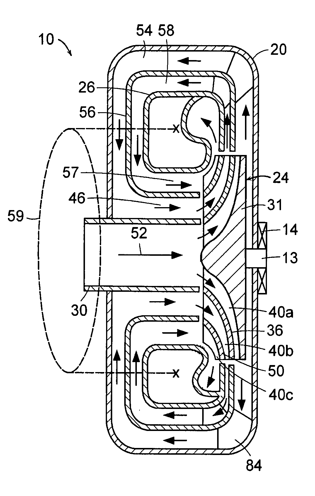
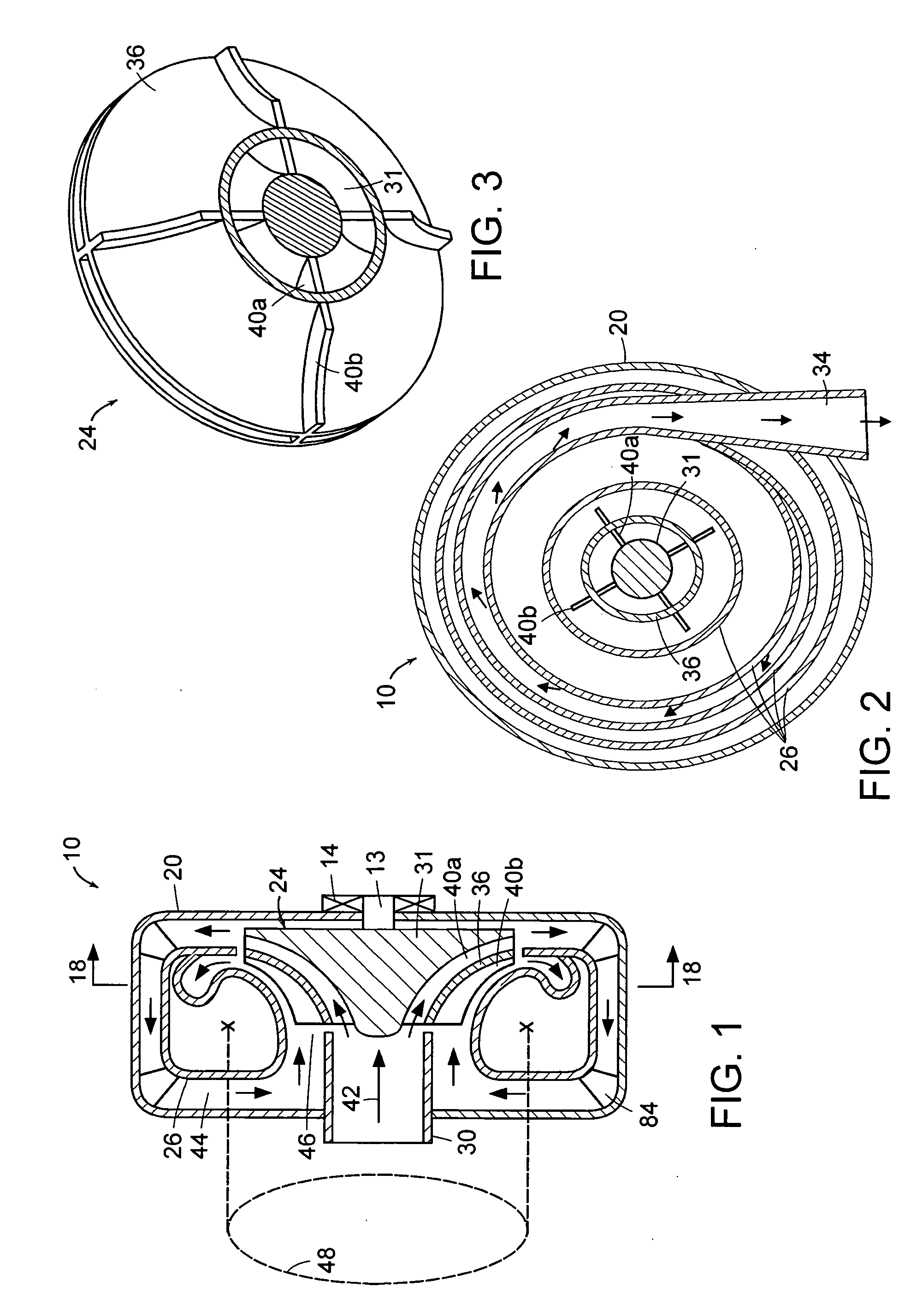
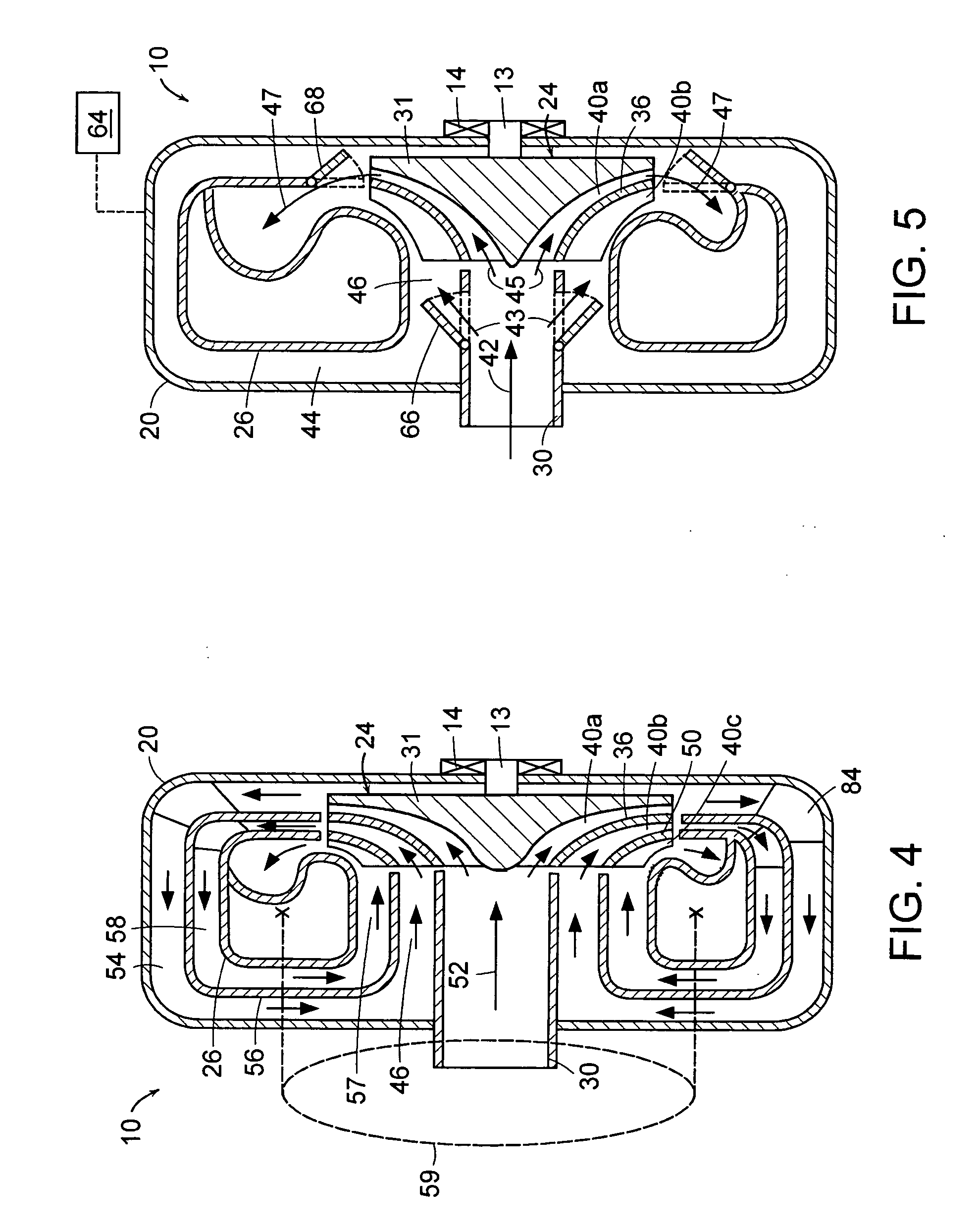
[0035] Turning to the drawings, exemplary configurations of fluid transfer controllers having rotor assemblies with multiple sets of rotor blades coupled to a common hub component are provided in FIGS. 1-14. In particular, fluid transfer controllers having rotor assemblies with multiple levels of rotor blades separated by partitions and successively stacked upon a common hub component are illustrated in FIGS. 1, 2, 4, 5, 7a, 7b, 8, 10, 11, 13, and 14. In addition, fluid transfer controllers having rotor assemblies with rotor blades coupled to opposing sides of a common hub component are illustrated in FIGS. 6a-8, and 12-14. FIG. 9 depicts a system having a plurality of fluid transfer controllers arranged in series at least one of which includes a configuration described in reference to FIGS. 1-8 and, as such, depicts at least one fluid transfer controller with multiple sets of rotor blades coupled to a common hub component. FIG. 3 depicts a perspective view of the rotor assembly dep...


PUM


Abstract

Fluid transfer controllers (FTCs) having a rotor assembly with multiple rotor blade sets coupled to a hub component of the rotor assembly and further having barrier components forming passages for routing fluid through the multiple rotor blade sets are provided. More specifically, the FTCs include passages for routing fluid along one side of a dividing structure to which a first set of rotor blades is attached and subsequently along the opposite side of the dividing structure to which a second set of rotor blades is attached. The dividing structure may be the hub component of the rotor assembly or a partition separating different levels of rotor blades within the rotor assembly. In some cases, the FTCs may be configured to route fluid from the first rotor blade set to a thermal energy alteration device and further route fluid from the thermal energy alteration device to the second rotor blade set.

Description

BACKGROUND OF THE INVENTION [0001] 1. Field of the Invention [0002] The present invention relates to fluid flow equipment, and more particularly, to fluid transfer controlling equipment such as compressors, pumps, blowers, and power generation devices (e.g., turbochargers and turbo-engines). [0003] 2. Description of the Related Art [0004] The following descriptions and examples are not admitted to be prior art by virtue of their inclusion within this section. [0005] Fluid transfer controllers are used for a variety of functions, including but not necessarily limited to compressing and pumping fluids as well as converting energy from flowing fluids for power generation devices. Exemplary applications for fluid transfer controllers with one or more of such functions include aircraft jet engines, industrial gas compressors, pipeline transports, refrigeration systems, as well as several others. In general, fluid transfer controlling equipment (referred to hereinafter as “fluid transfer ...

Claims


Application Information

Patent Timeline
IPC IPC(8): F04D29/44
CPCF04D17/12F04D29/4206F04D29/286F04D25/045
Inventor ABDALLAH, SHAABAN A.
Owner MACRO MICRO DEVICES
Why Eureka
Try Eureka