
Refrigeration cycle system

a cycle system and refrigeration technology, applied in the direction of machines/engines, positive displacement liquid engines, lighting and heating apparatus, etc., can solve the problems of failure to continue uncompressed operation, blade cannot be held retracted, etc., to prevent abnormal noise, no deterioration in system performance, no blade noise or damage, effect of preventing abnormal nois

Inactive Publication Date: 2007-07-05
TOSHIBA CARRIER CORP
View PDF11 Cites 30 Cited by
  • Summary
  • Abstract
  • Description
  • Claims
  • Application Information

AI Technical Summary

Benefits of technology

[0006] It is an object of the invention to provide a refrigeration cycle system capable of continuing the uncompressed operation while preventing noise and damage from causing to the blade.
[0014] According to the refrigeration cycle system of the characters mentioned above, there is equipped with a capacity regulating mechanism that allows the slider of a pressure regulating four-way valve, thus making it possible to vary the capacity of the compressor.
[0015] The location of such capacity variable mechanism causes no deterioration in the system performance. In addition, since the spring constant of the spring does not have to be reduced, the blade pressed by the spring at the high pressure during the normal operation is prevented from jumping, resulting in no generation of noise or damage to the blade. Furthermore, during the capacity regulated operation, a large difference in the pressure between the leading end and the back surface of the blade serves to maintain the blade within the cylinder blade groove, thus preventing abnormal noise owing to the jumping of the blade from causing. The capacity regulating mechanism may be operated during the system operation, resulting in improved comfort and energy saving effects. In the system, since the high pressure refrigerant in the sealed case does not leak to the suction side, the capacity regulating mechanism is capable of reducing the leakage loss to zero. This makes it possible to continue the uncompressed operation.

Problems solved by technology

In the aforementioned case, the blade may jump (momentarily moving away from the roller) during the normal operation, resulting in the causing of noise or damage to the blade.
As a result, the blade cannot be held retracted, thus failing to continue the uncompressed operation.

Method used


Image

  • Refrigeration cycle system
  • Refrigeration cycle system
  • Refrigeration cycle system

Examples


Embodiment Construction

[0025] An embodiment of a refrigeration cycle system according to the present invention will be described hereunder with reference to the drawings.

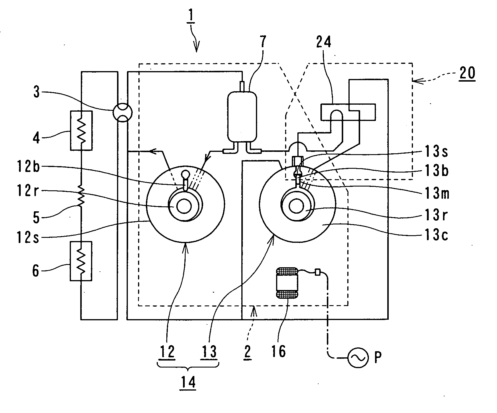
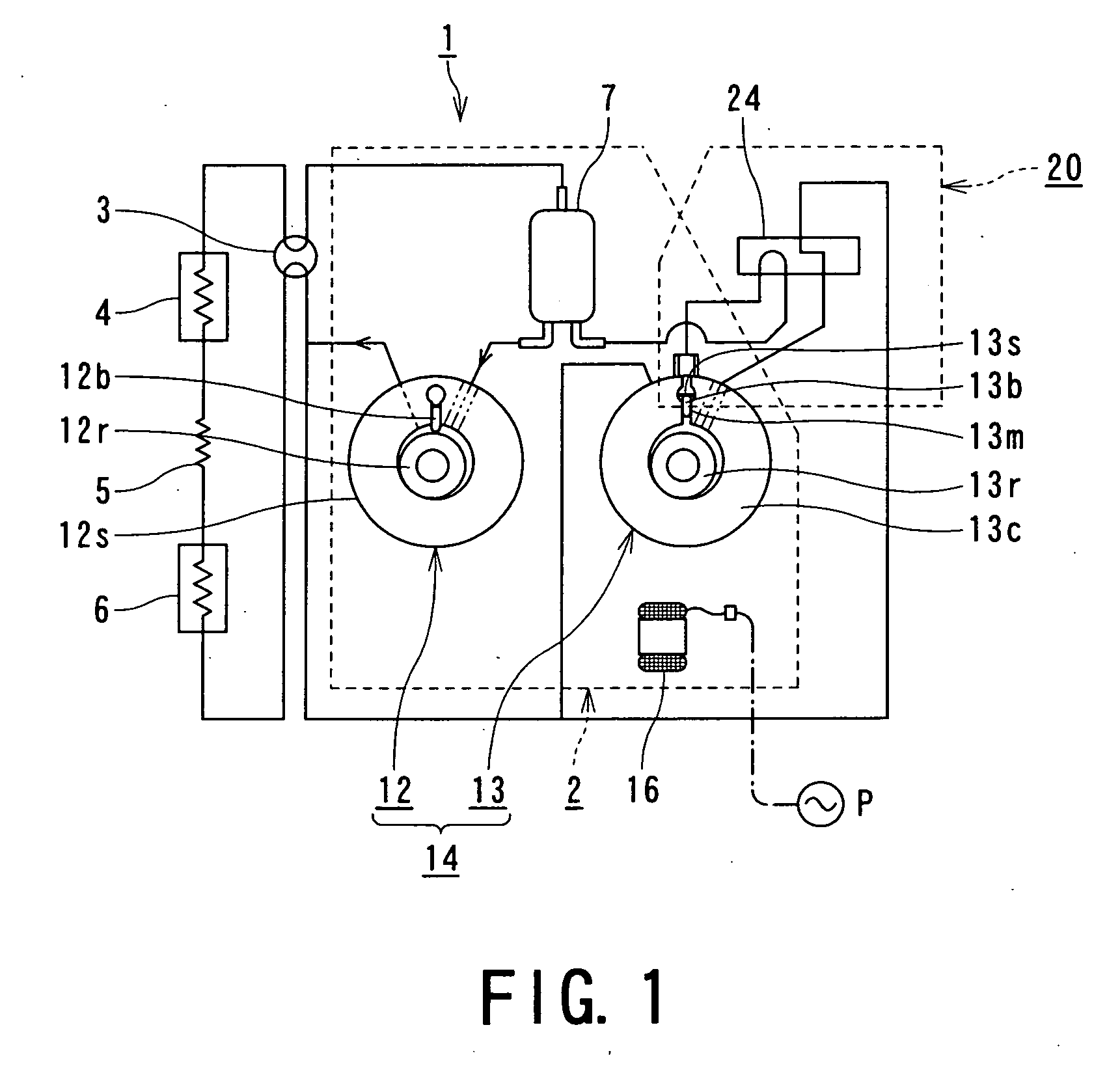
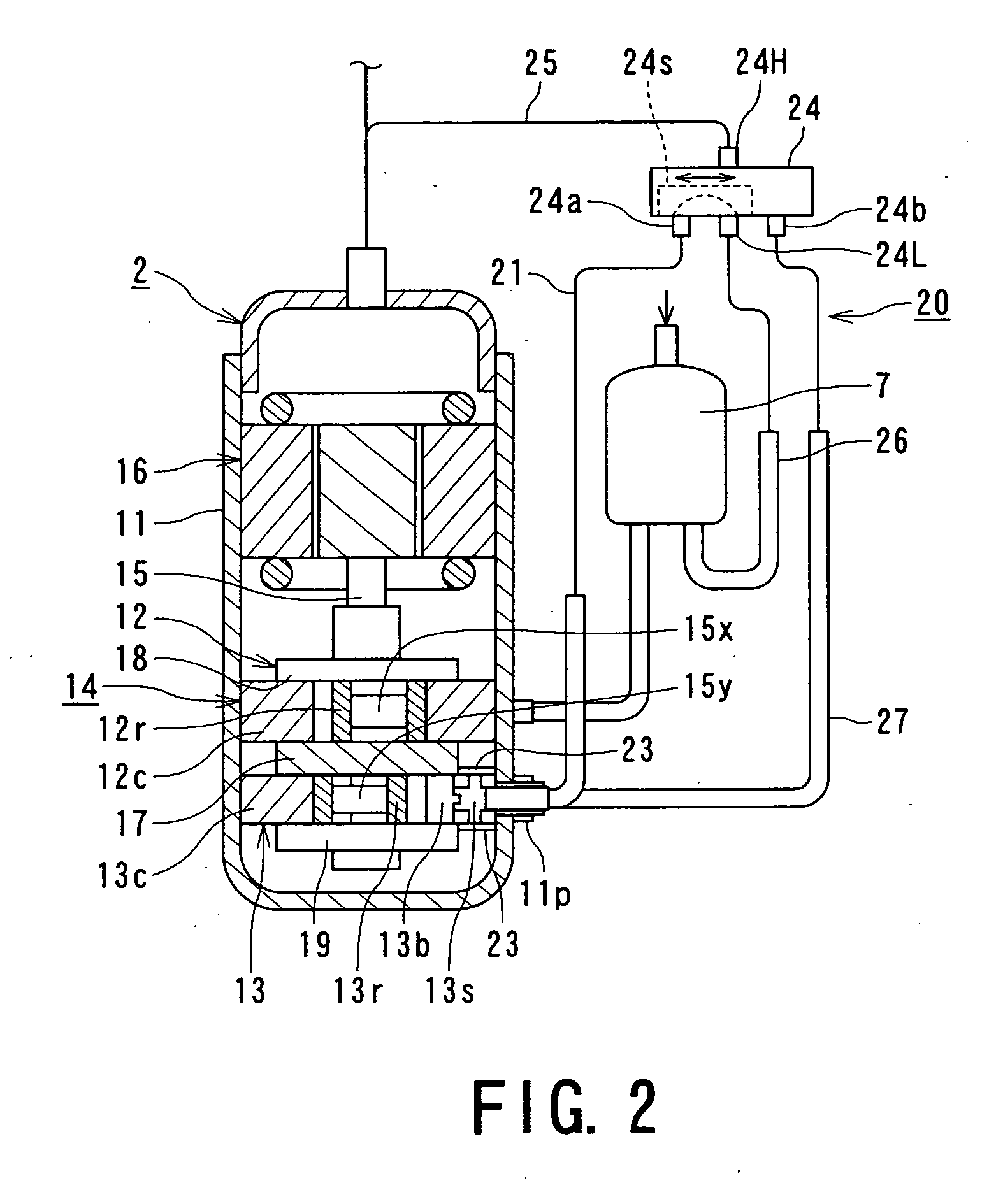
[0026]FIG. 1 is a conceptual view of the refrigeration cycle system according to the present invention. FIG. 2 is a vertical sectional view of a two-way cylinder rotor compressor employed for the refrigeration cycle system.

[0027] Referring to FIGS. 1 and 2, a refrigeration cycle system 1 is structured by connecting a vertical type two-way cylinder rotor compressor 2, a four-way valve 3 for switching between cooling and heating operations, an inner heat exchanger 4, a capillary tube 5 as an expander, an outer heat exchanger 6, and an accumulator 7 sequentially.

[0028] The compressor 2 includes a high pressure sealed case 11, a compression mechanism 14 composed of a first compression section 12 and a second compression section 13 stored in the sealed case 11, and an electric motor (motor mechanism) 16 that activates the compression mechan...


PUM


Abstract

A refrigeration cycle system is provided with a two-cylinder type rotary compressor having one compression mechanism which includes a switching mechanism for switching a back surface side of a blade between a low pressure mode and a high pressure mode and controlling the inner space of the cylinder chamber to the high pressure upon switching at the low pressure mode. In a high load state, a normal operation is performed by switching the pressure of the back surface side of the blade of the one compression mechanism at the high pressure mode. In a low load state, an uncompressed operation is performed by switching the pressure of the back surface side of the blade of the one compression mechanism at the low pressure mode and by controlling the inner space of the cylinder chamber to the high pressure to move the blade away from the roller. This makes it possible to provide the refrigeration cycle system which generates no noise and causes no damage to the blade, thus allowing the uncompressed operation to be continuously performed.

Description

TECHNICAL FIELD [0001] The present invention relates to a refrigeration cycle system equipped with a two-cylinder rotary compressor, and more particularly, to a refrigeration cycle system structured to perform an uncompressed operation of one of compression sections in a low load state for realizing the low performance operation. BACKGROUND ART [0002] Generally, a two-cylinder rotary compressor is structured to perform the uncompressed operation of one of compression mechanisms in the low load state for the low performance operation so as to improve the operation efficiency. [0003] Japanese Patent Application Laid-open Publication No. HEI 1-247786 (Patent Publication 1) discloses a system structured to set the pressure within a cylinder chamber at a high level, and the pressure within a back-pressure chamber on a back surface of a blade at a intermediate level, and to move the blade away from a roller by a pressure difference between the high pressure and the intermediate pressure f...

Claims


Application Information

Patent Timeline
IPC IPC(8): F04B49/00F01C21/08F04C23/00F04C28/06
CPCF01C21/0863F04C23/001F04C2270/56F04C28/06F04C23/008F04C23/00F25B49/00
Inventor ONODA, IZUMI
Owner TOSHIBA CARRIER CORP
Learn More