
Methods for monitoring the status of assays and immunoassays

a technology for immunoassays and assays, applied in the field of methods for monitoring the status of assays and immunoassays, can solve the problems of inability to send blood samples to the hospital laboratory, incompatibility of protocols, personnel and equipment available in the hospital emergency department, and inability to meet the needs of assay results in a rapid tim

Inactive Publication Date: 2007-07-05
BIOSITE INC
View PDF72 Cites 29 Cited by
  • Summary
  • Abstract
  • Description
  • Claims
  • Application Information

AI Technical Summary

Benefits of technology

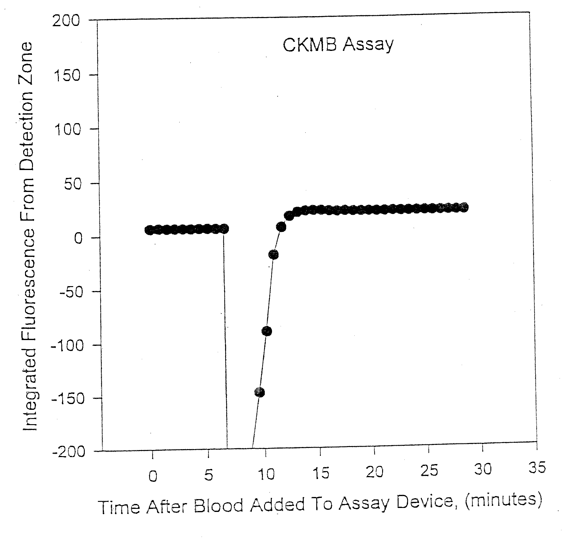
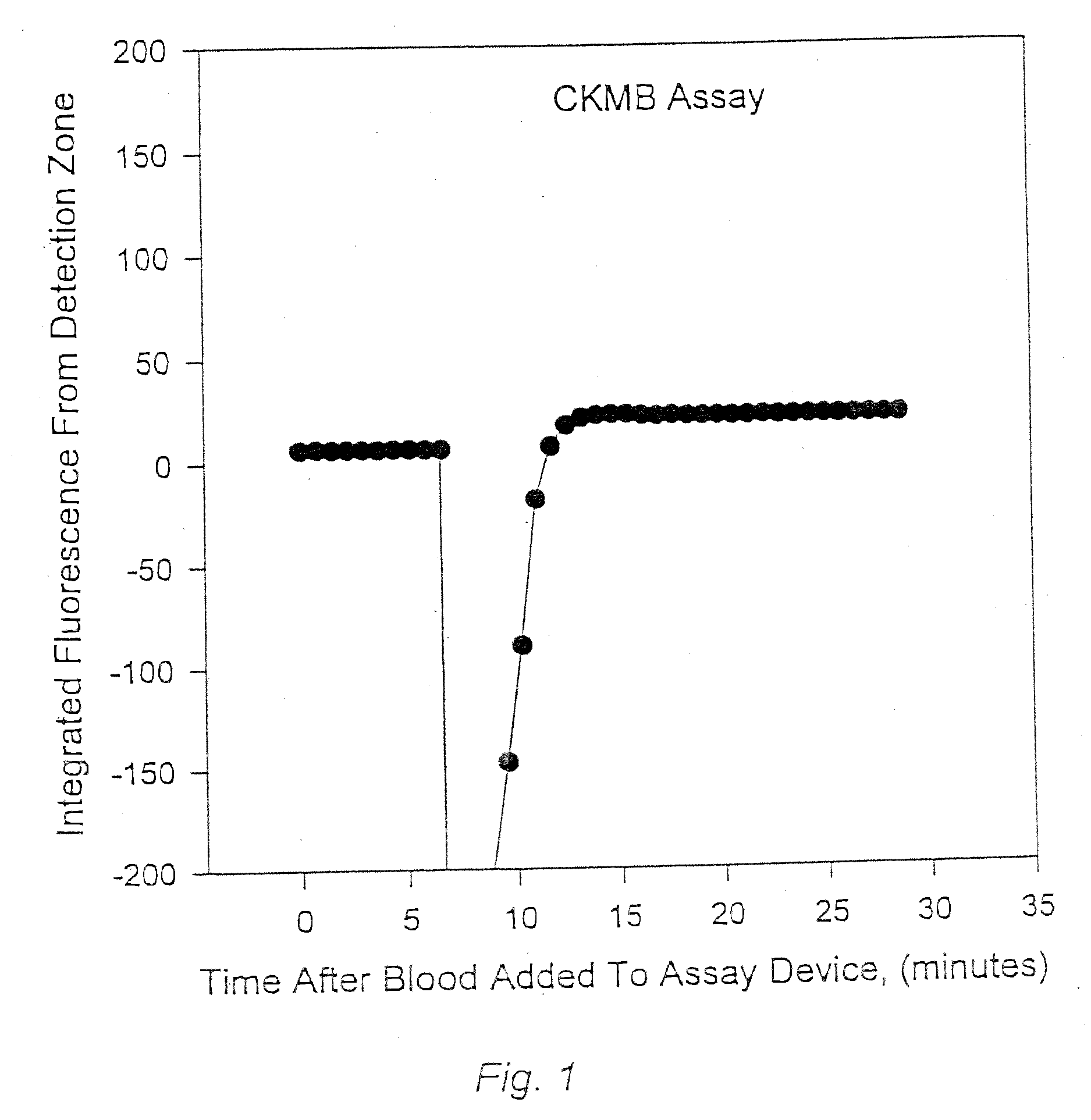
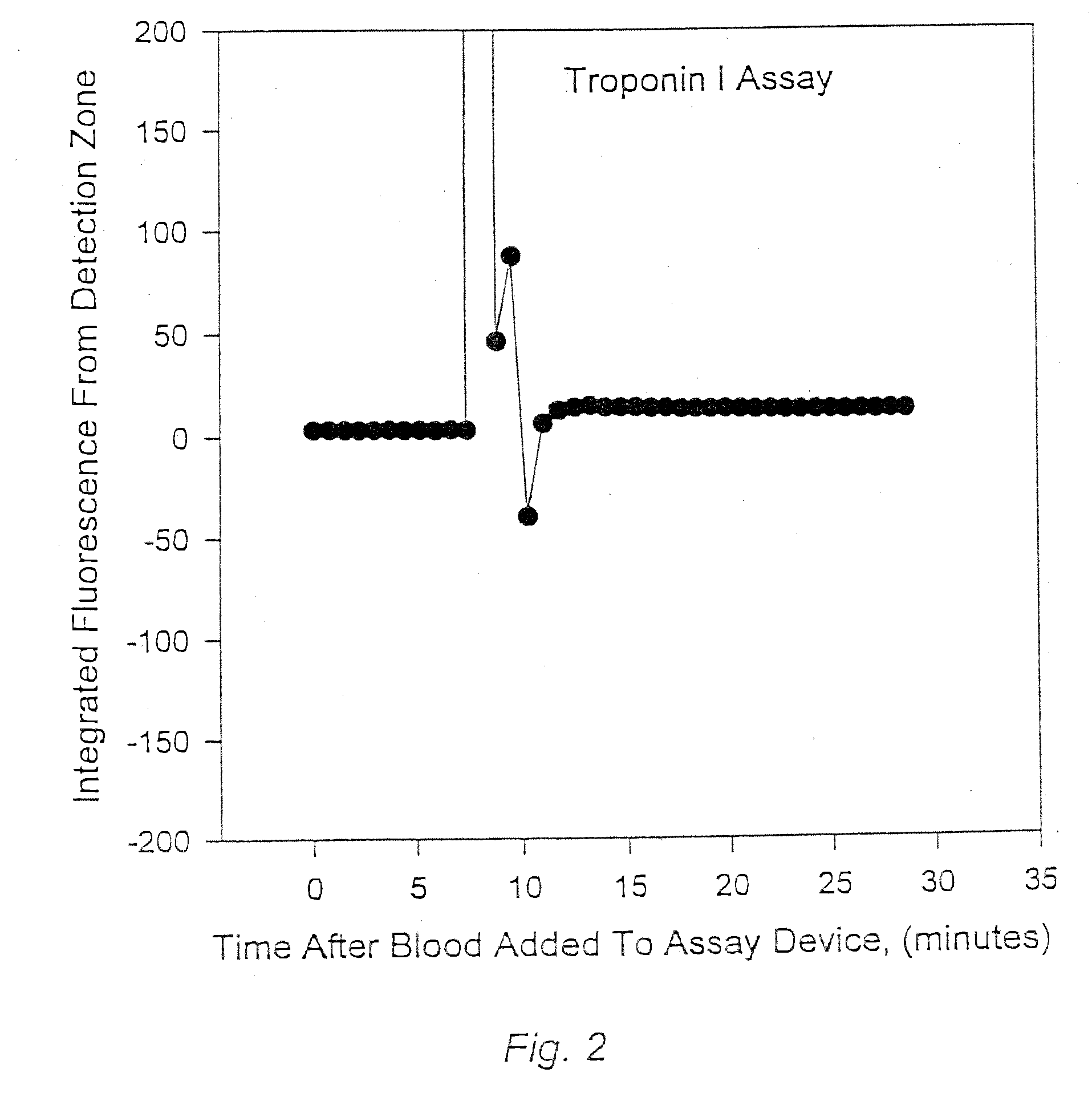
[0072] In another aspect, the invention features an apparatus for smoothing assay signal determinations in an assay device. The kit may comprise: (a) the assay device, which comprises a reaction chamber and at least one diagnostic lane; (b) an optical component; and (c) a signal processor, A label may be provided in the reaction chamber, where the label does not appreciably bind to any assay reagents in the assay device. The optical component may detect the signal in the diagnostic lane, where the signal is generated from the label. The signal processor may smooth the signal.
[0073] In yet another aspect, the invention features a kit for smoothing assay signal determinations in an assay device. The kit may comprise: (a) at least one of a Food and Drug Administration Label and a set of instructions; and (b) an apparatus, comprising: (i) the assay device, comprising a reaction chamber and at least one diagnostic lane; (ii) an optical component; and (iii) a signal processor. A label may be provided in the reaction chamber, where the label does not appreciably bind to any assay reagents in the assay device. The optical component may detect the signal in the diagnostic lane, where the signal is generated from the label. The signal processor may smooth the signal. IAC for Verifying the Location of a Detection Zone

Problems solved by technology

The current practice of sending blood samples to the hospital laboratory is not feasible when the results are required within 30 min.
The problem is thus that assay results are needed in a rapid time but the testing protocols, personnel and equipment available to the hospital emergency department are not compatible with this need.

Method used


Image

  • Methods for monitoring the status of assays and immunoassays
  • Methods for monitoring the status of assays and immunoassays
  • Methods for monitoring the status of assays and immunoassays

Examples


example 1

Preparation of Fluorescent Energy Transfer Latex with Bovine Serum Albumin (FETL-BSA) and Antibody (FETL-AB) Conjugates

[0187] Fluorescent energy transfer latex was prepared as described in U.S. patent application Ser. No. 08 / 409,298, filed 23 Mar. 1995 using silicon phthalocyanine bis(di-methylhexylvinylsilyloxide) and silicon [di(1,6-diphenylnaphthalocyanine)]diphthalocyanine bis(di-methylhexyvinylsilyloxide) as donor and acceptor dyes, respectively, at a ratio of 4 moles of donor to 1 mole of acceptor. The latex particles are about 230 nm in diameter and were purchased from Interfacial Dynamics Corporation. The FETL particles were adsorbed with bovine serum albumin (BSA) or various antibodies using techniques that are standard to one skilled in the art. Alternatively, the BSA or the antibodies were attached covalently to the particles using heterobifunctional crosslinking reagents (SMCC and SPDP, from Pierce Chemical Co.) also using techniques that are standard to one skilled in ...

example 2

Preparation of Flow Control FETL Conjugate for the Cardiac Marker Assay

[0189] To a solution of FETL-BSA, (11 ml at 1% solids, w / v, 220 nm particles), prepared according to example 1, was added with stirring, ascorbic acid and ethylenediamine tetraacetic acid to final concentrations of 20 mM and 0.1 mM, respectively. SMCC (3.8 μl of a 60 mM solution in acetonitrile) was added with stirring and the solution was incubated at room temperature for 2 h. The reaction was quenched by addition of 0.45 ml of 0.5 M solution of taurine. The solution was applied to a gel filtration column and 23.1 ml FETL-BSA-maleimide was eluted. A solution of decapeptide thiol (19 μl of 4.7 mM solution) was added and the solution was incubated at room temperature for 50 min. Decapeptide thiol was prepared by hydrolysis in as described in Example 4. The solution was applied to a gel filtration column and the eluted FETL-BSA-decapeptide was centrifuged at top speed in an Eppendorf centrifuge for 20 min. The pel...

example 3

Preparation of Time Gate Control FETL Conjugate for the Cardiac Marker Assay

[0190] To a solution of FETL-BSA, (20 ml at 1% solids, w / v, 220 mm particles), prepared according to example 1, was added with stirring, ascorbic acid and ethylenediamine tetraacetic acid to final concentrations of 20 mM and 0.1 mM, respectively. SMCC (17 μl of a 60 mM solution in acetonitrile) was added to the solution, with stirring, and incubated at room temperature for 2 h. The reaction was quenched by addition of 0.82 ml of 0.5 M solution of taurine. The solution was applied to a gel filtration column and 16.9 ml of FETL-BSA-maleimide was eluted. Morphine-HCTL was synthesized and hydrolyzed to the corresponding thiol derivative as described in U.S. Pat. No. 5,089,391, Example 4, incorporated by reference. Morphine thiol (0.52 ml of a 16.3 mM solution) was added and the solution was incubated at room temperature for 3 h. The reaction was quenched by addition of N-ethyl maleimide to a final concentration...


PUM


Abstract

The invention relates in part to the use of independent assay controls (IACs) for the optical communication between an assay device and an instrument in monitoring and performing assays, preferably immunoassays.

Description

RELATED APPLICATIONS [0001] The present application is a continuation of application Ser. No. 09 / 003,065, filed Jan. 5, 1998, now U.S. Pat. No. 6,194,222, which is related to co-pending U.S. patent application Ser. No. 09 / 003,090, entitled “Immunoassay Fluorometer,” filed Jan. 5, 1998, and a U.S. Pat. No. 6,074,616, each of which are filed concurrently herewith and each of which are incorporated herein by reference in their entirety, including all figures, tables, and drawings.FIELD OF THE INVENTION [0002] This invention relates in part to the use of independent assay controls (IACs) for the optical communication between an assay device and an instrument in monitoring and performing assays, preferably immunoassays. BACKGROUND OF THE INVENTION [0003] The development of reliable methods for rapidly and simply measuring analytes in complex samples has become increasingly important. For example, the point of care testing in hospital emergency departments requires unskilled technicians t...

Claims


Application Information

Patent Timeline
IPC IPC(8): G01N33/53G01N11/04G01N33/543G01N33/558G01N35/00G06K9/00
CPCG01N11/04Y10S436/818G01N33/54306G01N35/00693G01N2011/008G01N2021/6439G01N2035/00702Y10S435/81Y10S435/967Y10S435/97Y10S435/805Y10S436/81Y10S436/805Y10S435/971G01N33/53
Inventor BUECHLER, KENNETH F.ANDERBERG, JOSEPH M.MCPHERSON, PAUL H.
Owner BIOSITE INC
Learn More