
Coupler With Improved Jaw Configuration
- Summary
- Abstract
- Description
- Claims
- Application Information
AI Technical Summary
Benefits of technology
Problems solved by technology
Method used
Image

Examples
Embodiment Construction
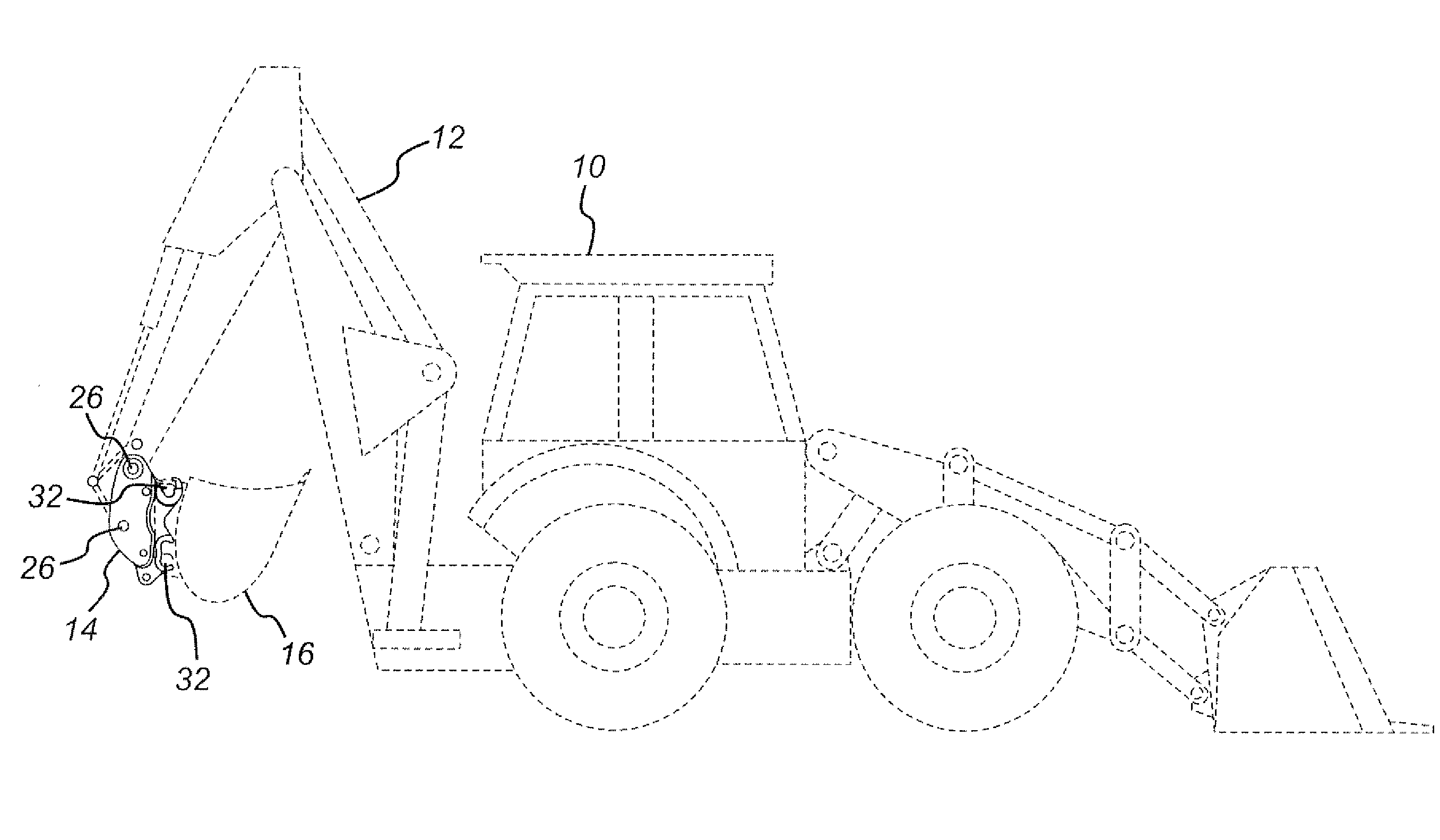
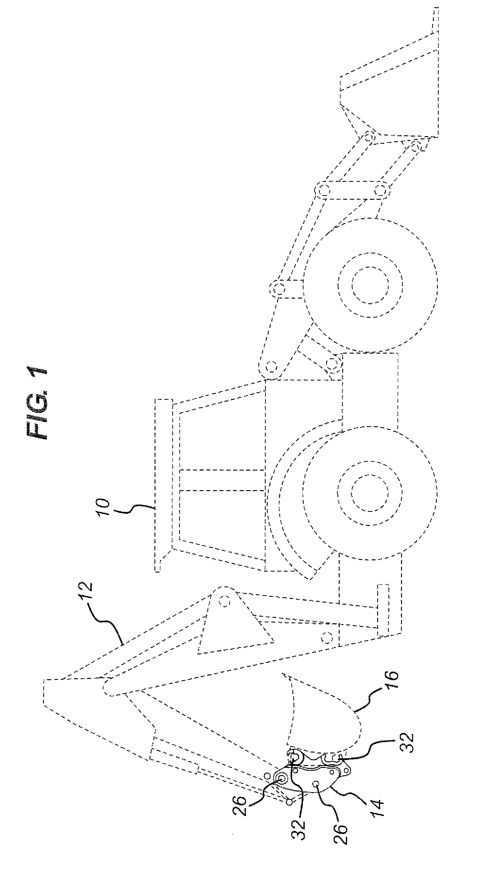
[0060] Referring first of all to FIG. 1, the excavator digger 10 has a rear excavator arm 12. The arm 12 has a coupler 14 of the present invention attached thereto by way of pins, as known in the art. The coupler 14 attaches a bucket 16 to the excavator arm 12 of the digger 10 again by way of pins, as known in the art. The excavator arm 12, the bucket 16 and the digger 10 are all shown in dotted lines since only the coupler is of interest in the present case.
[0061] Instead of a bucket 16, some alternative excavator attachment might be secured to the excavator arm 12 of the digger 10 by the coupler 14.
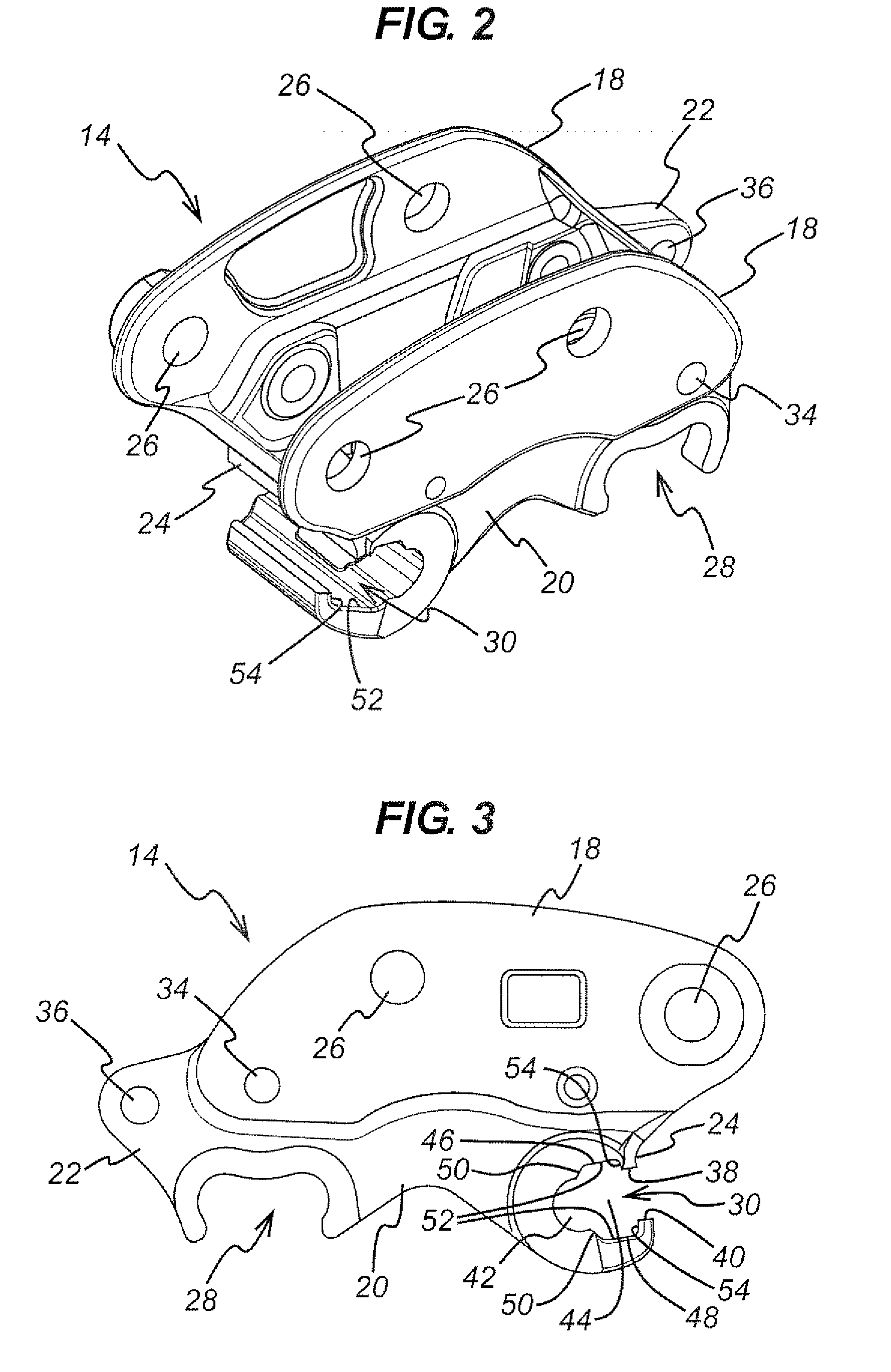
[0062] As shown in FIGS. 2 to 5, the coupler 14 comprises a top portion 18, a bottom portion 20, and two ends 22, 24. In normal use, the front end 24 is the one that is shown to the right in FIG. 3 and the rear end 22 is the one that is shown to the left in FIG. 3. The front end 24 is therefore the end that would usually point towards the digger when the digger operator is attempting ...
PUM
 Abstract
Description
Claims
Application Information