
Plastic film sealing blade

a sealing blade and plastic film technology, applied in the direction of packaging, metal working equipment, etc., can solve the problems of deteriorating the quality and appearance of packaged goods, affecting the sealing edge, and observing irregular sealing edges

Inactive Publication Date: 2007-07-12
BENISON
View PDF15 Cites 8 Cited by
  • Summary
  • Abstract
  • Description
  • Claims
  • Application Information

AI Technical Summary

Benefits of technology

[0007] An objective of the present invention is to provide a plastic film sealing blade having an edge facing coming direction of a plastic film, a notch being formed in the edge to smoothly guide and cut off the plastic film, thereby making straight and smooth sealing edge along the plastic film.
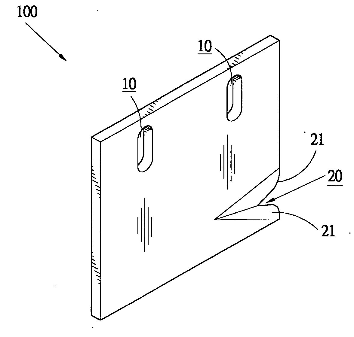
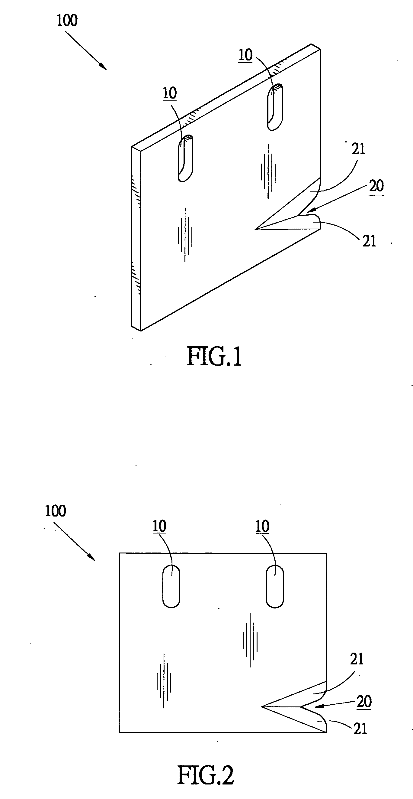
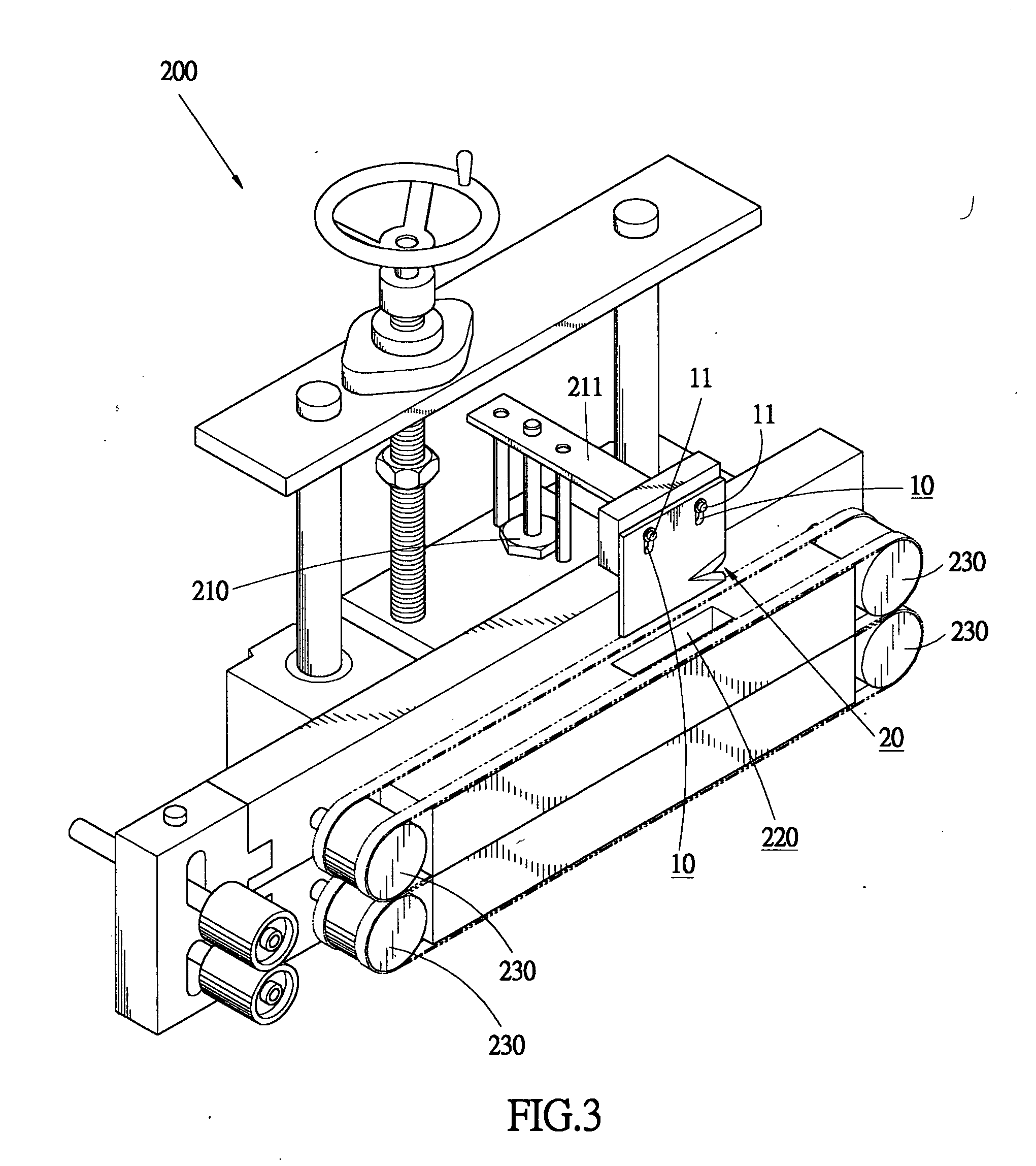
[0009] To achieve the above-mentioned objectives, in accordance with the present invention, a plastic film sealing blade is provided, comprising a board body having opposite primary faces and an edge. Slots are defined in the board for fixing the sealing blade to the side sealing mechanism whereby the sealing blade is movable by the side sealing mechanism to a cutting position. The edge forms a V-shaped cutting notch delimited by opposite sharp edge sections, each having an edge line from which an inclined face extends to each primary face of the board to thereby guide and cut a plastic film moving in the given direction
[0010] In accordance with the present invention, the notch and the sharp edge sections delimiting the notch function to guide, flatten, and cut a plastic film and uniformly heating and thus forming a high-quality sealing edge of the plastic film.

Problems solved by technology

Due to the facts that plastic film is not always maintained in a straight and tight condition, and that the area of the sealing blade for performing sealing operation on the film is large, non-uniform, skewed and irregular sealing edge is commonly observed in the goods packaged by plastic film by the conventional sealing device.
This deteriorates the quality and appearance of the packaged goods.

Method used


Image

  • Plastic film sealing blade
  • Plastic film sealing blade
  • Plastic film sealing blade

Examples


Embodiment Construction

[0018] With reference to the drawings and in particular to FIGS. 1 and 2, a sealing blade constructed in accordance with the present invention, generally designated with reference numeral 100, comprises a flat-board-like body having opposite primary surfaces defining a thickness of the boar. A plurality of connecting slots 10 is defined in the blade 100. The slots 10 can be of any desired shaped and are preferably elongated. A cutoff or notch 20 is defined in a front edge of the board. The notch 20 can be of any desired shaped, but is preferably a V-shape as illustrated in the drawings. The V-shaped notch 20 is delimited by two sharp edge sections 21, each edge section having an edge line and opposite inclined faces extending from the edge line to the primary faces of the board respectively. Alternatively, the edge line may be coincident with one of the primary face and the sharp edge section 21 has only one inclined face extending from the edge line to the opposite primary face of ...


PUM


Abstract

A plastic film sealing blade is mounted to a side sealing mechanism for cutting and sealing a plastic film moving in a given direction. The sealing blade includes a board body having opposite primary faces and an edge. Slots are defined in the board for fixing the sealing blade to the side sealing mechanism whereby the sealing blade is movable by the side sealing mechanism to a cutting position. The edge forms a V-shaped cutting notch delimited by opposite sharp edge sections, each having an edge line from which an inclined face extends to each primary face of the board to thereby guide and cut a plastic film moving in the given direction.

Description

BACKGROUND OF THE INVENTION [0001] 1. Field of the Invention [0002] The present invention generally relates to the field of side sealing device for plastic packaging films, and in particular to a sealing / cutting blade of the side sealing device that forms a notch having sharp edge sections to facilitate guiding and cutting of the plastic packaging film. [0003] 2. The Related Art [0004] Heat-shrinkage films made of plastics are commonly used in packaging goods for purposes of decoration and protection. For example, the plastic film is used to pack such as CDs that are enclosed in plastic cases and books. The plastic film is also used to package food to keep freshness and protect of the packaged food. A plastic film sealing device is employed to package these goods with the plastic film. The plastic film that wraps the goods is often sealed along front, rear, and lateral sides of the packaged goods. Thus, the packaging efficiency and quality is determined by the sealing operation alon...

Claims


Application Information

Patent Timeline
IPC IPC(8): B65B7/06
CPCB26D1/0006B26D1/025B26D7/0625B26D7/10B26D2001/006B29C66/849B29C65/7873B29C66/8167B29C66/8223B29C66/836B29C65/7439B29C65/18B29C66/43B29C66/137
Inventor LIAO, BENKER P.C.
Owner BENISON
Learn More