

Apparatus for testing a rupture strength of a pipe
- Summary
- Abstract
- Description
- Claims
- Application Information
AI Technical Summary
Benefits of technology
Problems solved by technology
Method used
Image

Examples
first embodiment
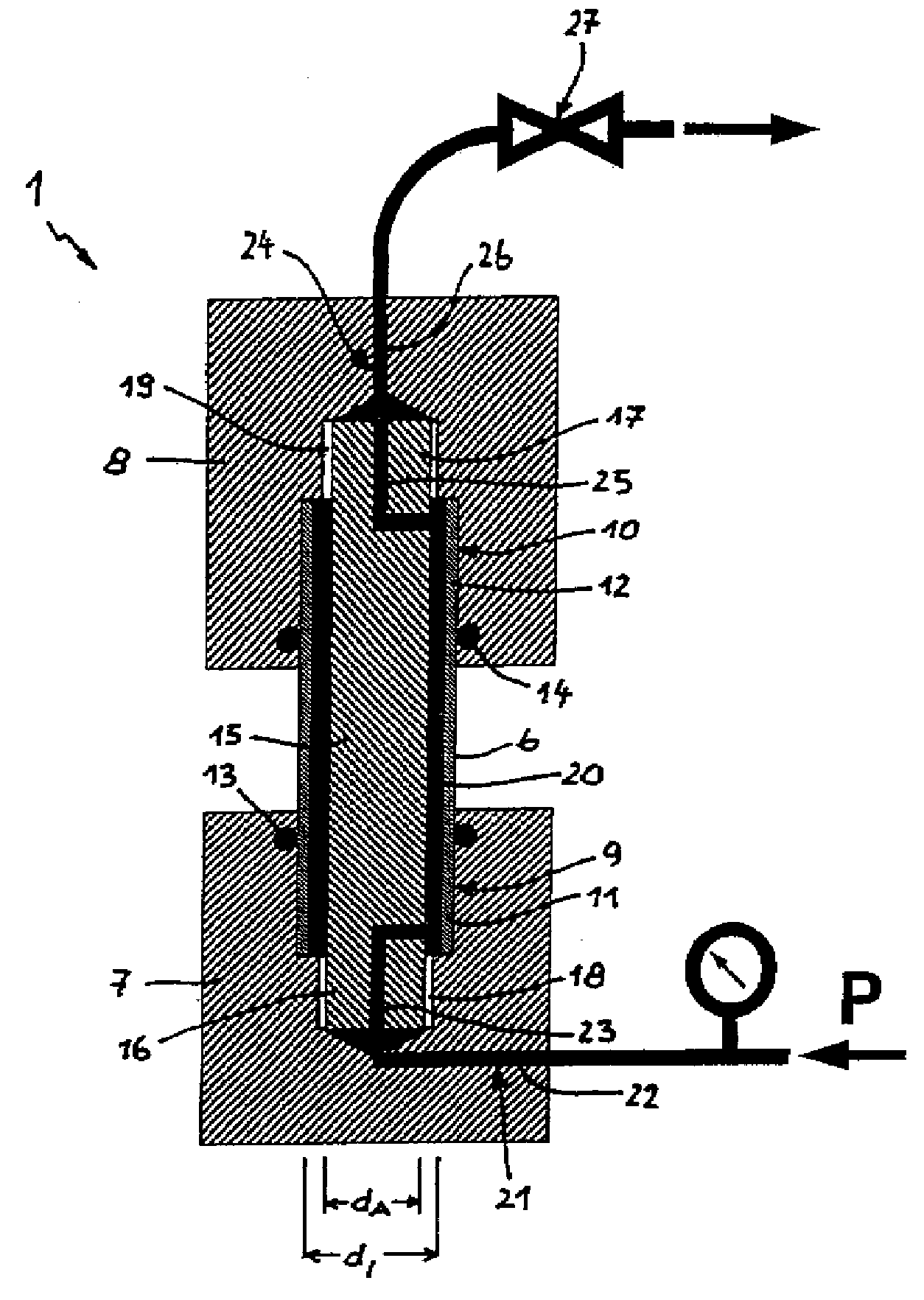
[0023]Turning now to the drawing, and in particular to FIG. 1, there is shown a schematic sectional view of a pipe testing apparatus according to the present invention, generally designated by reference numeral 1, for carrying out a stress-rupture test. The rupture device 1 includes a lower clamping head 7 with a cylindrical receptacle 9 for sealingly accepting one end 11 of a pipe 6, and an upper clamping head 8 with a cylindrical receptacle 10 for sealingly accepting another end 12 of the pipe 6, Seals 13, 14 are disposed in the receptacles 9, 10 to provide a sealing between the receptacles 9, 10 and the ends 11, 12 of the pipe 6.
[0024]The clamping heads 7, 8 are connected by a central tie rod 15 which extends through the pipe 6 in coaxial relationship thereto. The tie rod 15 has opposite threaded ends 16, 17 which are secured in threaded sockets 18, 19 of the lower and upper clamping heads 7, 8, respectively. The threaded sockets 18, 19 are provided in the clamping heads 7, 8 bel...
second embodiment
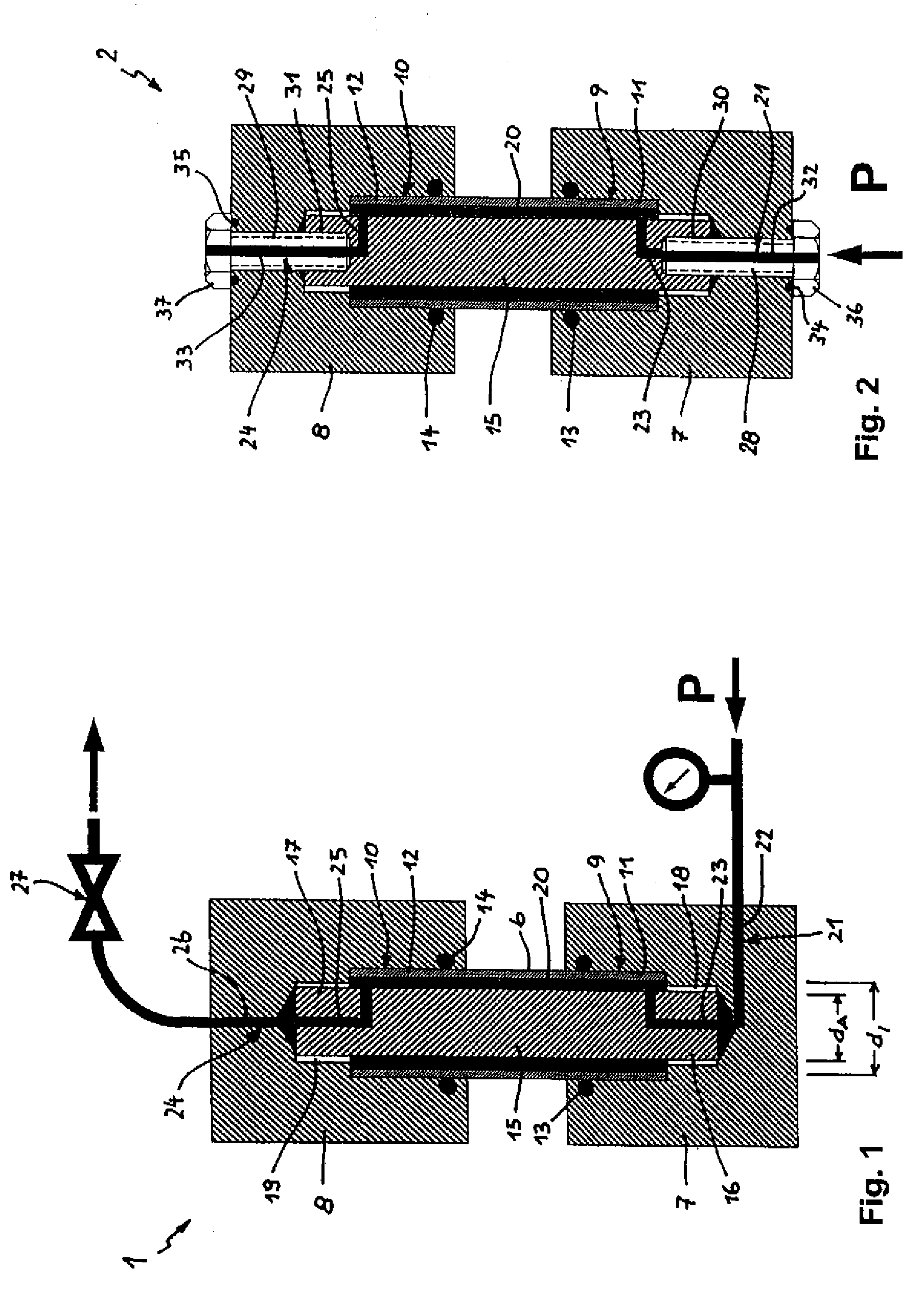
[0031]Referring now to FIG. 2, there is shown a schematic sectional view of a pipe testing apparatus according to the present invention, generally designated by reference numeral 2. Parts corresponding with those in FIG. 1 are denoted by identical reference numerals and not explained again. The description below will center on the differences between the embodiments. In this embodiment, provision is made for tension bolts 28, 29 in order to secure the tie rod 15 in the lower and upper clamping heads 7, 8. The tension bolts 28, 29 extend in longitudinal direction of the tie rod 15 through the clamping heads 7, 8 and are screwed into threaded bores 30, 31 of the tie rod 15.
[0032]The feed channel 21 has a channel section 32, which extends through the tension bolt 28, and the vent channel 24 has a channel section 33, which extends through the tension bolt 29. Also in this embodiment, the feed channel 21 has a channel section 23 and the vent channel 24 has a channel section 25, with both...
third embodiment
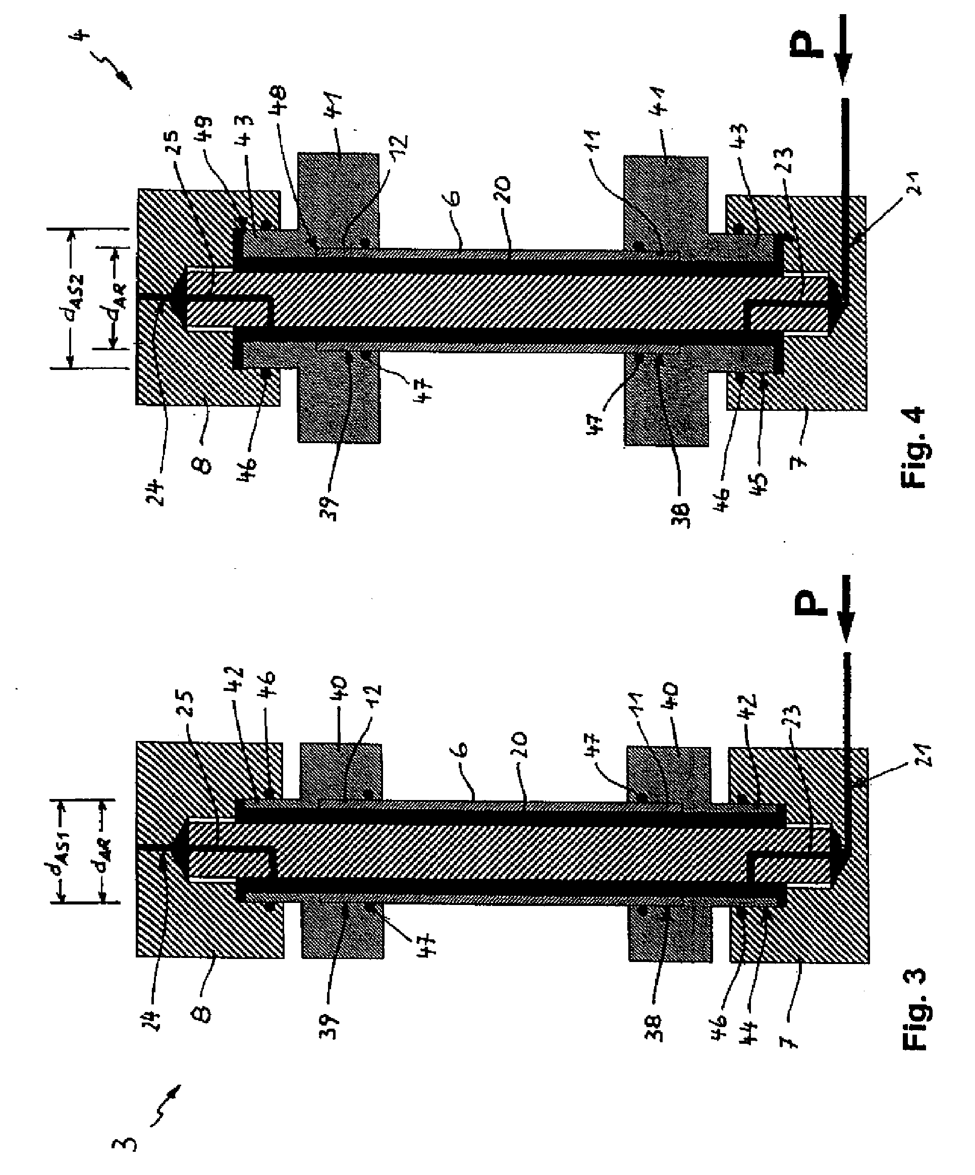
[0034]Referring now to FIG. 3, there is shown a schematic sectional view of a pipe testing apparatus according to the present invention, generally designated by reference numeral 3. Parts corresponding with those in FIG. 1 are denoted by identical reference numerals and not explained again. The description below will center on the differences between the embodiments. In this embodiment, the ends 11, 12 of the pipe 6 are received in receptacles 38, 39 which are formed in adapters 40, 41, respectively. The adapter 40 is hereby axially movably mounted in the clamping head 7, whereas the adapter 41 is axially movably mounted in the clamping head 8. The adapter 40 has a necking 42 which is supported in a pocket 44 of the lower clamping head 7, and the adapter 41 has a necking 43 which is supported in a pocket 45 of the upper clamping head 8. Seals 46, 47 are placed between the sockets 44, 45 and the neckings 42, 43 as well as between the pipe 6 and the receptacles 38, 39 in the adapters ...
PUM
 Abstract
Description
Claims
Application Information