

Dispensing cartridge
a cartridge and cartridge body technology, applied in the field of cartridges, can solve the problems that the user might be inconvenienced by the inability to remove the entire cartridge b>1/b> from the mixing unit, and achieve the effect of saving space in the closed applicator uni
- Summary
- Abstract
- Description
- Claims
- Application Information
AI Technical Summary
Benefits of technology
Problems solved by technology
Method used
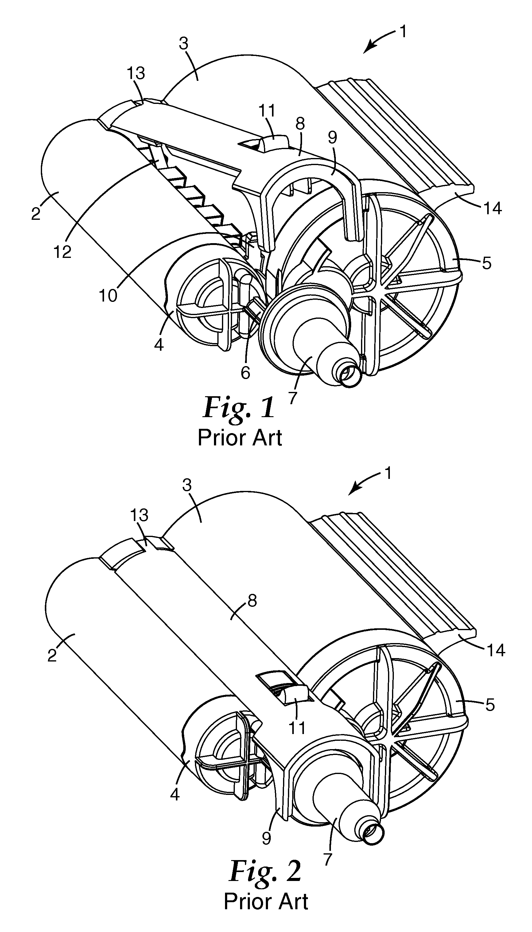
Image

Examples
Embodiment Construction
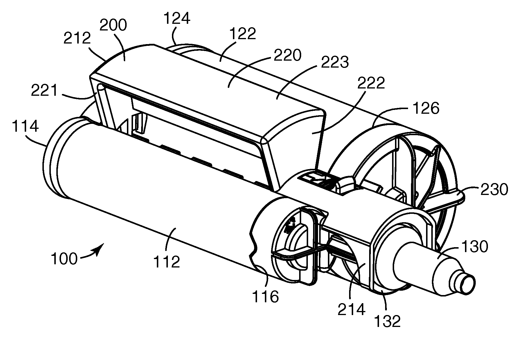
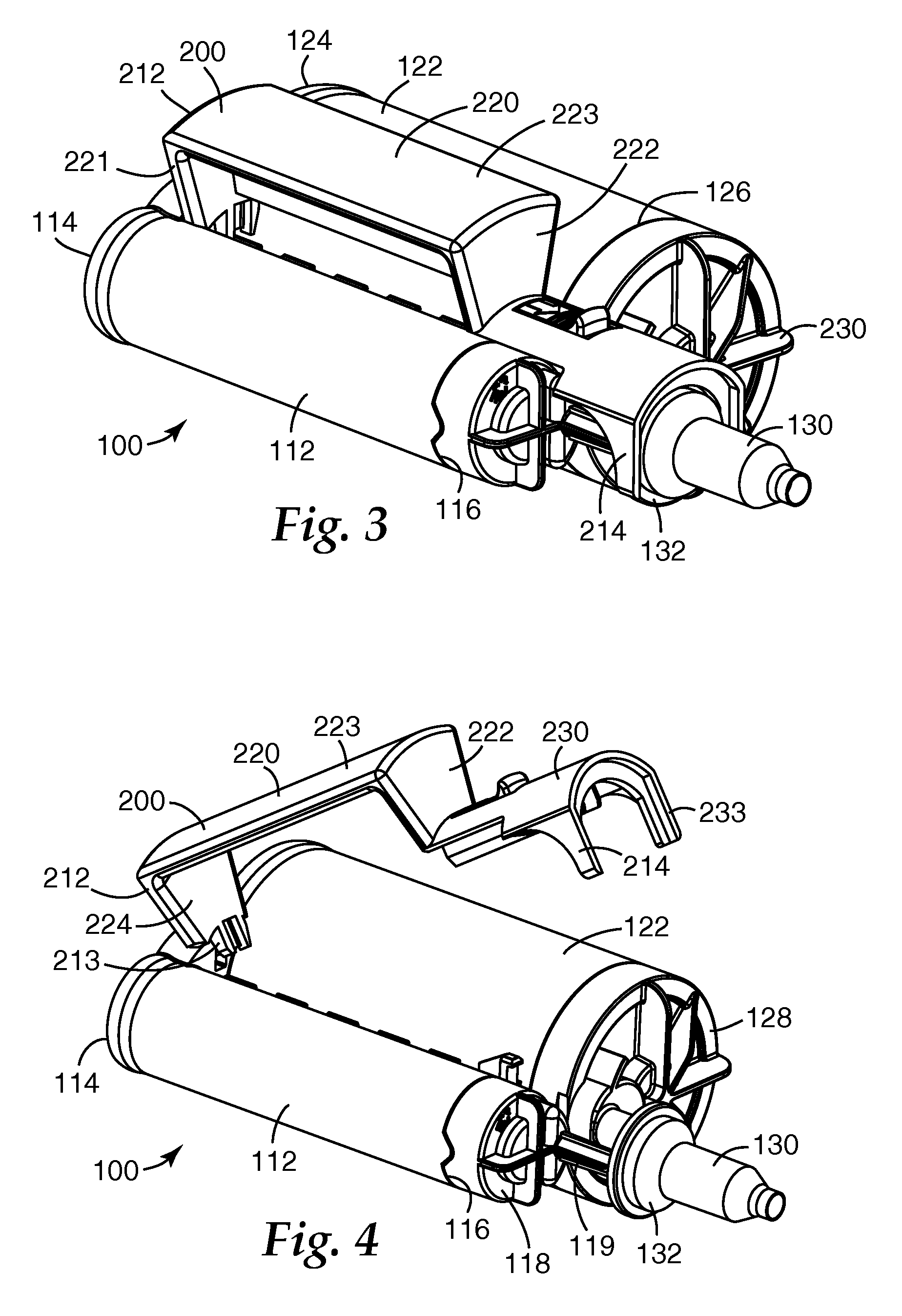
[0044] An example of a dispensing cartridge of a first embodiment of the invention is illustrated in FIGS. 3 and 4, and is designated by reference numeral 100. The cartridge 100 according to this embodiment comprises a first compartment with a body 112. Specifically, the body 112 includes a rear open end 114 and a front outlet opening 116 that is spaced from the open end 114. The compartment is elongated and extends from the rear open end 114 to the outlet opening 116.
[0045] The dispensing cartridge as shown in the Figures comprises a second compartment having a body 122. The body 122 includes a rear open end 124 and a front outlet opening 126 that is remote from the open end 124. The second compartment is elongated and extends from the open end 124 to the outlet opening 126.
[0046] In the illustrated embodiment, the dispensing cartridge 100 comprises a locking member 200 in the form of a pivotable lever arm that is connected at its rear end to the dispensing cartridge 100. Locking...
PUM
 Abstract
Description
Claims
Application Information