Antenna

Active Publication Date: 2007-07-12
WISTRON NEWEB
View PDF4 Cites 17 Cited by
  • Summary
  • Abstract
  • Description
  • Claims
  • Application Information

AI Technical Summary

Benefits of technology

[0009] The invention provides a wider band via a minor antenna. The invention is compatible with various communication standards, such as AMPS(824˜894 MHz) {grave over ( )} PCS(1850˜1990 MHz) {grave over ( )} GSM(880˜960 MHz) {grav

Problems solved by technology

The conventional flat antenna 1, however, has a narrow bandwidth, poor compatibility, and decreased transmission speed, such that it cannot satisfy wide

Method used


Image

  • Antenna
  • Antenna
  • Antenna

Examples


first embodiment

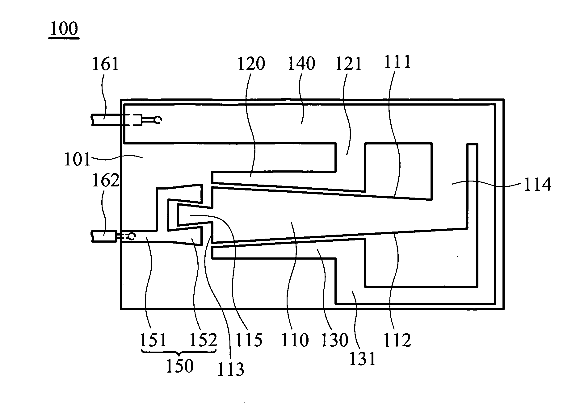
[0035]FIG. 2a shows an antenna 100 of the invention, a flat antenna. The antenna 100 comprises a first transmission element 110, a first conductive element 114, a second transmission element 120, a second conductive element 121, a third transmission element 130, a third conductive element 131, a ground element 140 and a feed element 150. The antenna 100 is a pattern formed on a circuit board 101, such as a flexible printed circuit board (FPC). The antenna 100 can also be a metal sheet independent of the circuit board. The ground element 140 is electrically connected to a ground line 161. The first transmission element 110 is connected to the first conductive element 114, and the first conductive element 114 is connected to the ground element 140. The first transmission element 110 is thus electrically connected to the ground element 140. The second transmission element 120 is connected to the second conductive element 121, and the second conductive element 121 is connected to the gr...

second embodiment

[0045]FIG. 5 shows an antenna 200 of the invention, wherein the first side 111′ and the second side 112′ are symmetrical stepped structures. The second transmission element 120′ comprises a stepped portion corresponding to the first side 111′, and the third transmission element 130′ comprises a stepped portion corresponding to the second side 112′.

third embodiment

[0046]FIG. 6 shows an antenna 300 of the invention, wherein the conductor 151′ is angled.


PUM


Abstract

An antenna comprises a ground element, a first transmission element, a feed element, a second transmission element and a third transmission element. The first transmission element is electrically connected to the ground element, wherein the first transmission element comprises at least one coupling portion, a first side and a second side. The feed element corresponds to the coupling portion. The second transmission element corresponds to the first side and is electrically connected to the ground element. The third transmission element corresponds to the second side and is electrically connected to the ground element. When a first wireless signal is transmitted, the feed element couples to the first transmission element to transmit the first wireless signal. When a second wireless signal is transmitted, the feed element couples to the first transmission element, and the second and third transmission elements couple to the first transmission element to transmit the second wireless signal.

Description

BACKGROUND OF THE INVENTION [0001] 1. Field of the Invention [0002] The invention relates to an antenna, and in particular to a wideband antenna. [0003] 2. Description of the Related Art [0004] GSM 900 and DCS 1800 signals are widely utilized in cell phone communication to transmit audio and visual data. FIG. 1a shows a conventional flat antenna 1 to transmit GSM 900 and DCS 1800 signals, disposed in a cell phone, comprising a radiator 2 and a signal line 3. The signal line 3 is electrically connected to the radiator 2. With reference to FIG. 1b, when the flat antenna 1 transmits GSM 900 signal, a bandwidth thereof (bandwidth is defined as signals having voltage standing wave ratios lower than 4) is about 70 to 80 MHz, and when the flat antenna 1 transmits DCS 1800 signal, a bandwidth thereof is about 140 to 150 MHz. [0005] Wireless communication, particularly long distance wireless transmission and wideband transmission, has become a necessary feature for portable electronic device...

Claims


Application Information

Patent Timeline
IPC IPC(8): H01Q1/38H01Q5/357
CPCH01Q1/243H01Q1/38H01Q5/357H01Q9/42H01Q9/0421
Inventor TSAI, FENG-CHI EDDIETSENG, KUAN HSUEH
Owner WISTRON NEWEB
Why Eureka
Try Eureka