Video optimized LCD response time compensation

Active Publication Date: 2007-07-12
DELL PROD LP
View PDF15 Cites 37 Cited by
  • Summary
  • Abstract
  • Description
  • Claims
  • Application Information

AI Technical Summary

Benefits of technology

[0012] In various embodiments of the invention, an incoming compressed video stream is decoded and motion vectors are parsed from each macroblock. The resulting motion vectors are then stored in a tile address generation block. Using video window coordinates, the tile address generation block computes frame buffer screen coordinates for each tile, corresponding to video stream macroblocks with non-

Problems solved by technology

In the past, video content viewed on LCD panels was generally of low quality and/or resolution, and typically limited to game graphics, Internet video streams, and file-based video clips.
However, the same characteristics that are well suited for display of static content are undesirable for display of video that contains motion.
In general, this is due to the inadequate pixel response times of liquid crystal display (LCD) panels.
Due to their electro-optical nature, the liquid crystal materials used in LCD panels have inertia and cannot be switched instantaneously.
This results in transition response times that are generally not fast enough for high quality video applications.
This slow response time, or latency, can result in video motion artifacts that cause quickly moving objects to appear visually blurred, an effect known as “ghosting” or “smearing.”
LCD response times continue to improve, but vendor specifications are generally limited to “off-to-on,”“rise a

Method used


Image

  • Video optimized LCD response time compensation
  • Video optimized LCD response time compensation
  • Video optimized LCD response time compensation

Examples


Embodiment Construction

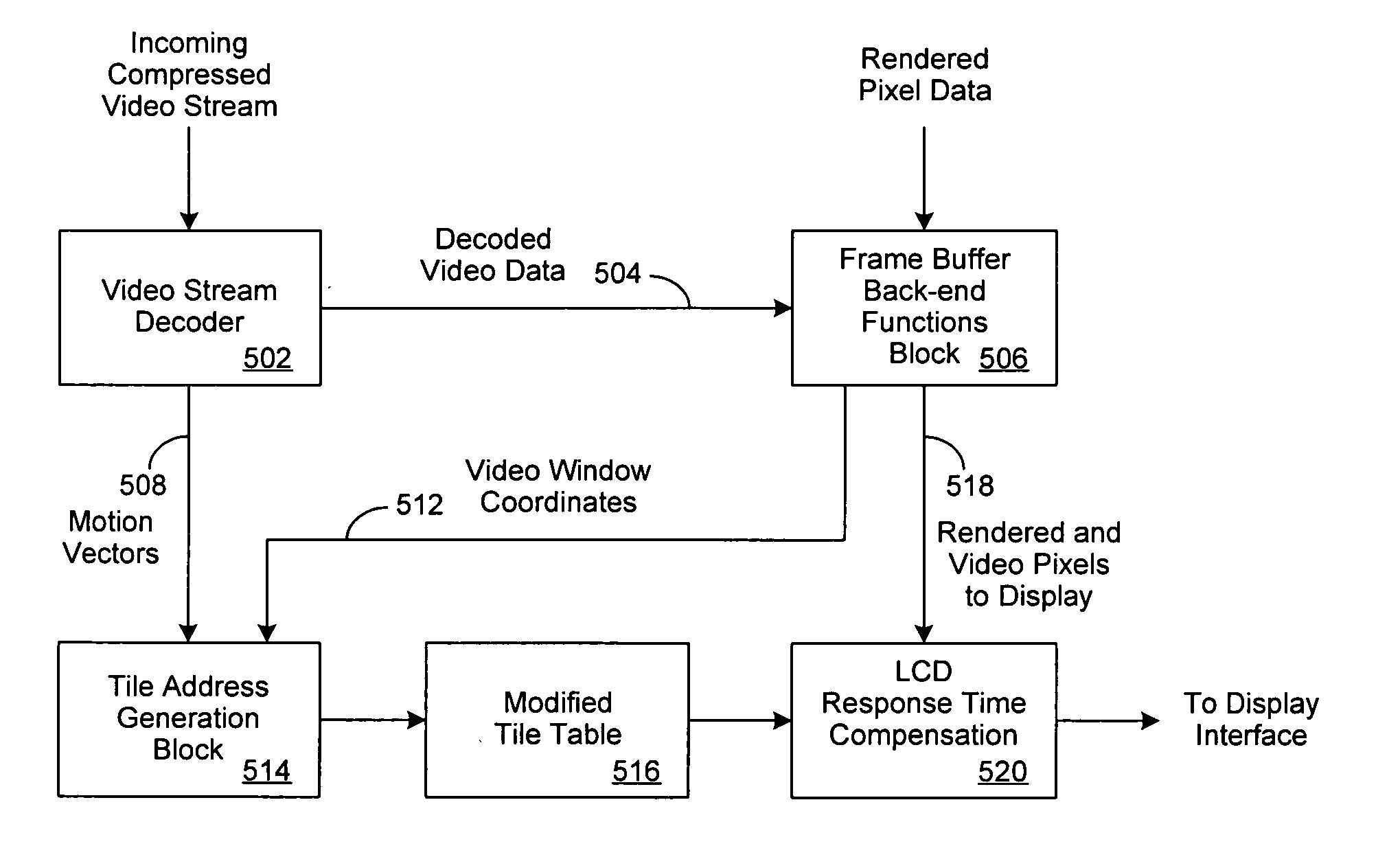
[0020] The present invention provides a video optimizer to improve the display of motion video data on an information handling system. As discussed in greater detail below, the video optimizer of the present invention utilizes motion vectors contained within macroblocks in a compressed video stream to selectively apply LCD Response Time Compensation (LRTC) to areas of an LCD panel containing video motion.

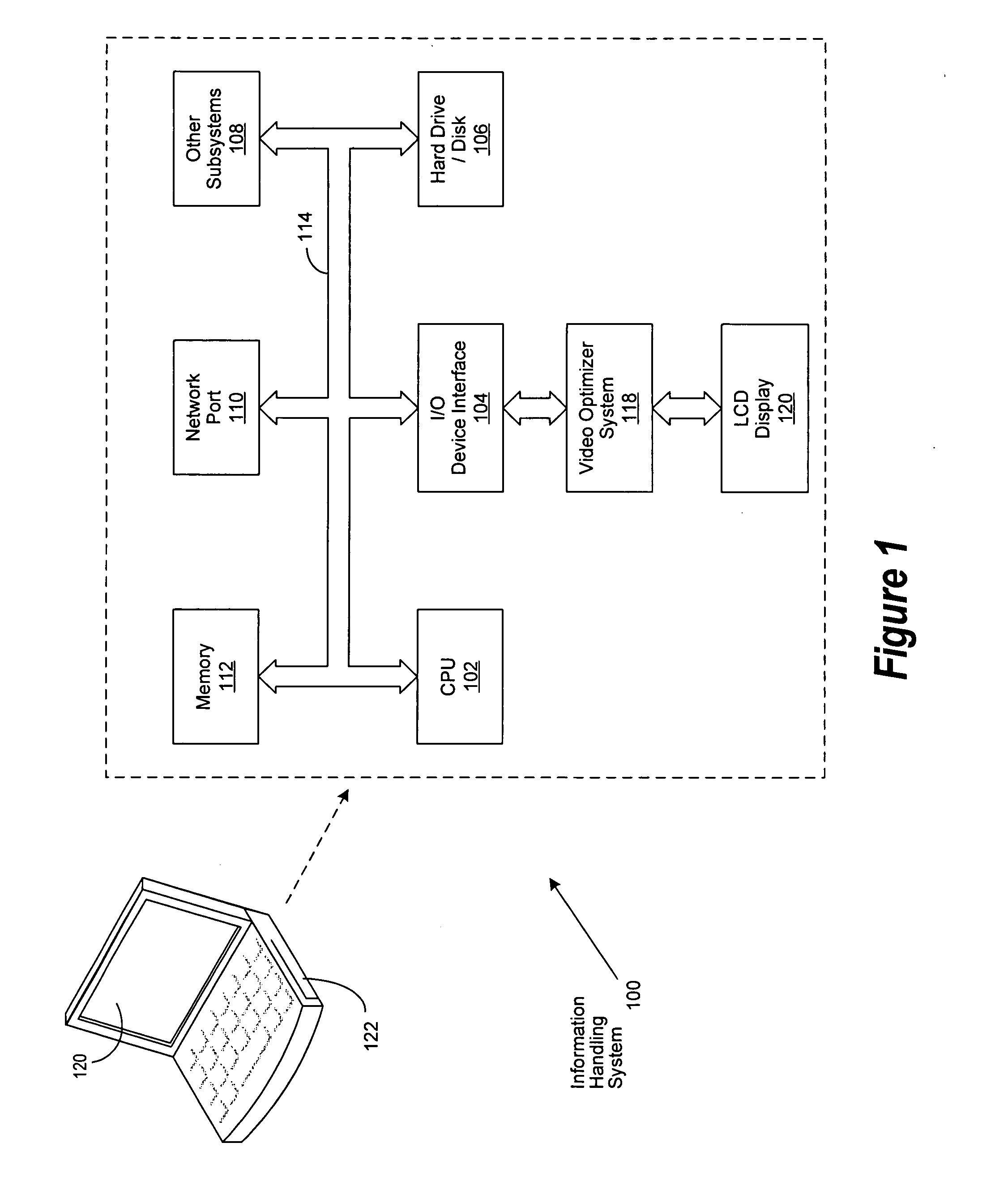
[0021] For purposes of this disclosure, an information handling system may include any instrumentality or aggregate of instrumentalities operable to compute, classify, process, transmit, receive, retrieve, originate, switch, store, display, manifest, detect, record, reproduce, handle, or utilize any form of information, intelligence, or data for business, scientific, control, or other purposes. For example, an information handling system may be a personal computer, a network storage device, or any other suitable device and may vary in size, shape, performance, functionality, and pr...


PUM


Abstract

An improved system and method for selectively applying LCD Response Time Compensation (LRTC) to areas of an LCD panel containing video motion. Motion vectors contained within macroblocks in a compressed video stream are utilized to qualify whether individual pixels in a video frame are a candidate for LRTC. In various embodiments of the invention, computationally expensive LRTC can be selectively applied, pixel-by-pixel, which can result in portable information system power savings by reducing the number of computational cycles and the amount of graphics controller power overhead.

Description

BACKGROUND OF THE INVENTION [0001] 1. Field of the Invention [0002] The present invention relates in general to the field of information handling system displays and, more particularly, to a system and method for improving the display of motion video on an LCD panel. [0003] 2. Description of the Related Art [0004] As the value and use of information continues to increase, individuals and businesses seek additional ways to process and store information. One option available to users is information handling systems. An information handling system generally processes, compiles, stores, and / or communicates information or data for business, personal, or other purposes thereby allowing users to take advantage of the value of the information. Because technology and information handling needs and requirements vary between different users or applications, information handling systems may also vary regarding what information is handled, how the information is handled, how much information is ...

Claims


Application Information

Patent Timeline
IPC IPC(8): G09G3/36
CPCG09G3/3611G09G2320/0252G09G2340/16G09G2320/106G09G2320/0261
Inventor KNEPPER, LAWRENCE E.JUENGER, RANDALL E.LANZONI, THOMAS P.
Owner DELL PROD LP
Why Eureka
Try Eureka