
Apparatus and method for driving LED

Active Publication Date: 2007-07-12
LG INNOTEK CO LTD
View PDF7 Cites 3 Cited by
  • Summary
  • Abstract
  • Description
  • Claims
  • Application Information

AI Technical Summary

Benefits of technology

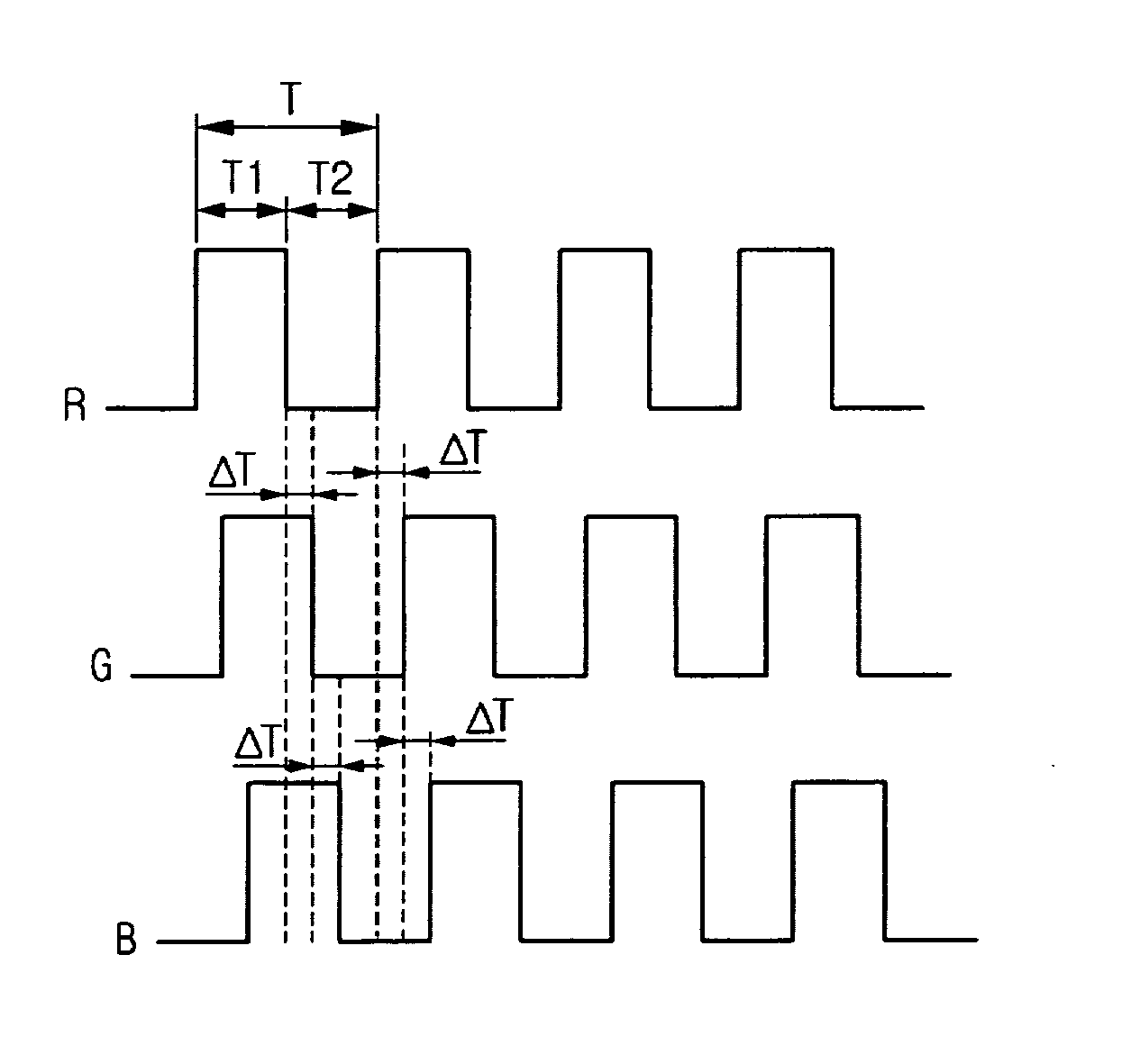
[0009] The embodiment of the present invention provides an apparatus and method for driving LEDs for reducing wave noise, which is caused by the LEDs, by sequentially turning on or off the LEDs that emits three colors.
[0012] The embodiment of the invention provides a method for driving a light emitting diode, the method comprising: detecting a state of a pulse; sequentially delaying a turn-on time of switching units to sequentially turn on red, green, and blue light emitting diodes when the pulse is changed in a first state; and sequentially delaying a turn-off time of switching units to sequentially turn off red, green, and blue light emitting diodes when the pulse is changed in a second state.
[0013] According to the present invention, wave noise can be reduced in a combined light by sequentially turning on or off LEDs emitting three colors.

Problems solved by technology

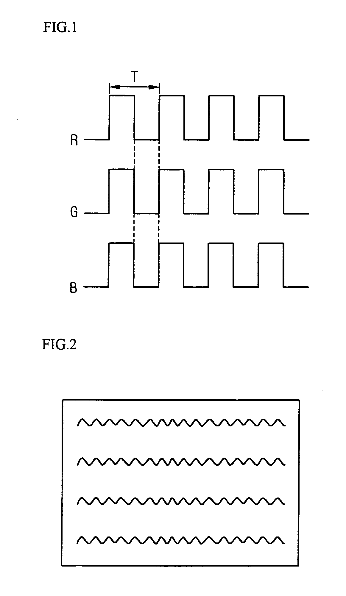
Accordingly, numerous compound harmonics occur such that wave noise in an output screen of an LCD panel of FIG. 2 is generated.

Method used


Image

  • Apparatus and method for driving LED
  • Apparatus and method for driving LED
  • Apparatus and method for driving LED

Examples


Embodiment Construction

[0020] Reference will now be made in detail to the preferred embodiments of the present invention, examples of which are illustrated in the accompanying drawings.

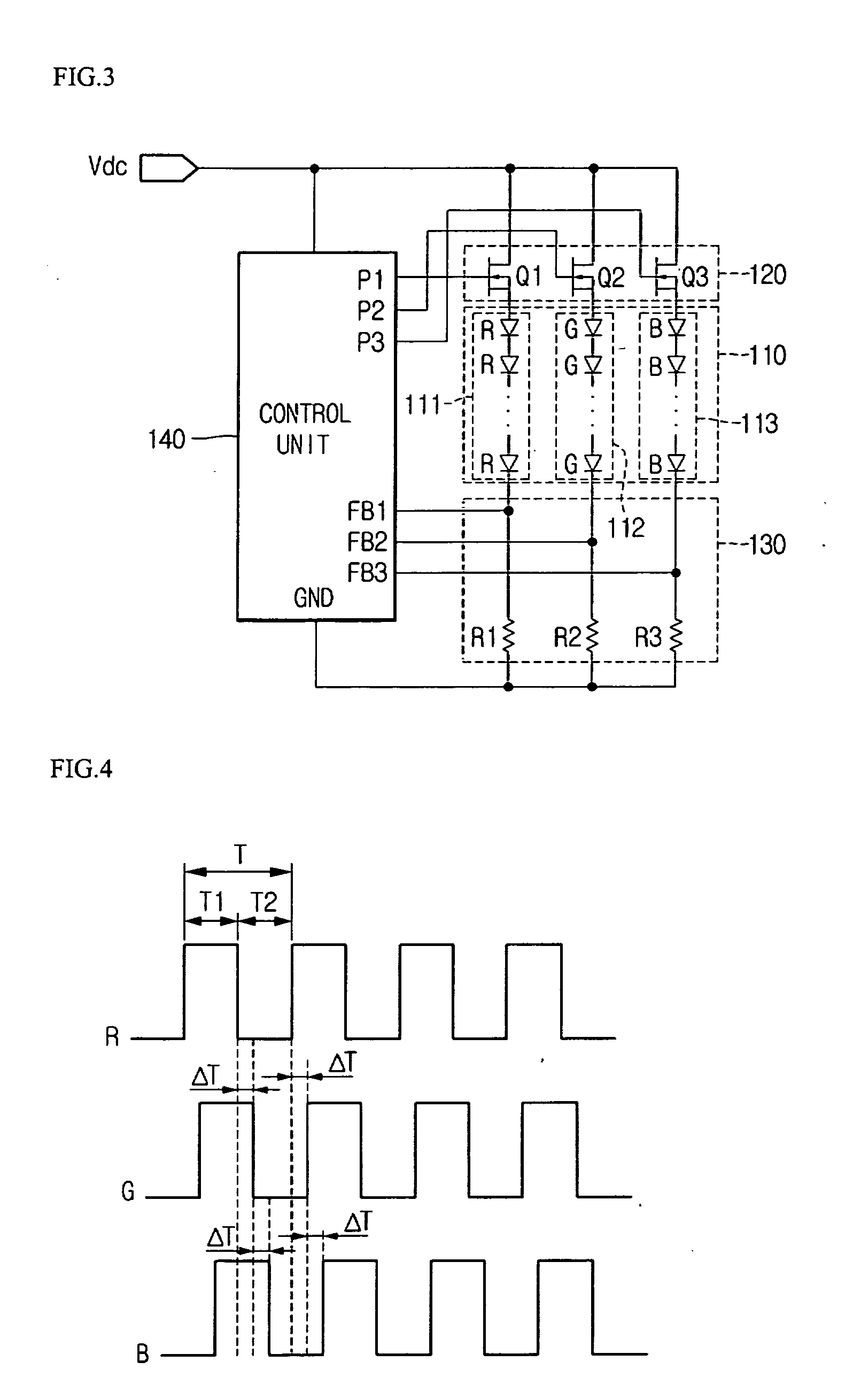
[0021]FIG. 3 is a view of an LED driving unit according to an embodiment of the present invention.

[0022] Referring to FIG. 3, the LED driving unit includes a light emitting unit 110, a switching unit 120, a feedback unit 130, and a control unit 140.

[0023] The light emitting unit 110 includes red, green, and blue LEDs 111, 112, and 113 to provide a white light. In the red LED 111, a plurality of red LED chips are connected in serial to each other. In the green LED 112, a plurality of green LED chips are connected in serial to each other. In the blue LED 113, a plurality of blue LED chips are connected in serial to each other.

[0024] Here, one of the red LED chips, one of the green LED chips, and one of the blue LED chips constitute a cluster in a package. A plurality of clusters are disposed to form one module. Additional...


PUM


Abstract

Provided are an apparatus and method for driving LEDs. The apparatus comprise a plurality of red, green, and blue light emitting diodes connected, respectively; switching units turned on or off by an inputted pulse to turn on or off the red, green and blue light emitting diodes, respectively; and a control unit outputting respective pulses to sequentially delay a turn-on or turn-off time between the switching units.

Description

BACKGROUND OF THE INVENTION [0001] 1. Field of the Invention [0002] The present invention relates to an apparatus and method for driving a light emitting diode (LED). [0003] 2. Description of the Related Art [0004] LEDs are widely used as a light source of a backlight unit in a liquid crystal display (LCD) device to enhance a color reproduction and a high brightness. [0005] The backlight unit includes an edge type and a direct type according to a method of using a light source. In the edge type, a light source is installed on a side of a light guiding plate. The edge type is applied to a relatively small sized LCD device such as a computer monitor. The direct type is applied to a relatively large sized LCD device such as larger than a 20 inch monitor. [0006] The backlight unit includes a plurality of arrays for lights of red, green, and blue LEDs. Driving pulses are supplied into red LED, green LED, and blue LED, respectively. A white light including red, green, and blue lights is u...

Claims


Application Information

Patent Timeline
IPC IPC(8): G09G5/00G09G3/14
CPCG09G3/3413G09G2320/0242G09G2310/0235Y10S257/918E05B15/00E05B65/00E05C9/02
Inventor PARK, SEONG SOO
Owner LG INNOTEK CO LTD
Learn More