Moving image coding apparatus, moving image decoding apparatus, control method therefor, computer program, and computer-readable storage medium

Active Publication Date: 2007-07-12
CANON KK
View PDF34 Cites 43 Cited by
  • Summary
  • Abstract
  • Description
  • Claims
  • Application Information

AI Technical Summary

Benefits of technology

[0018] The present invention has been made to solve the above problems, and has as its object to provide a technique of preventing errors from being gradually accumulated on the decoding side, while

Problems solved by technology

According to this scheme, it is impossible to reduce the code amount.
In this case, when the information of a portion which has been referred to for motion compensation is lost by abortion of bitplane coding, errors due to motion compensation are accumu

Method used


Image

  • Moving image coding apparatus, moving image decoding apparatus, control method therefor, computer program, and computer-readable storage medium
  • Moving image coding apparatus, moving image decoding apparatus, control method therefor, computer program, and computer-readable storage medium
  • Moving image coding apparatus, moving image decoding apparatus, control method therefor, computer program, and computer-readable storage medium

Examples


Example

First Embodiment

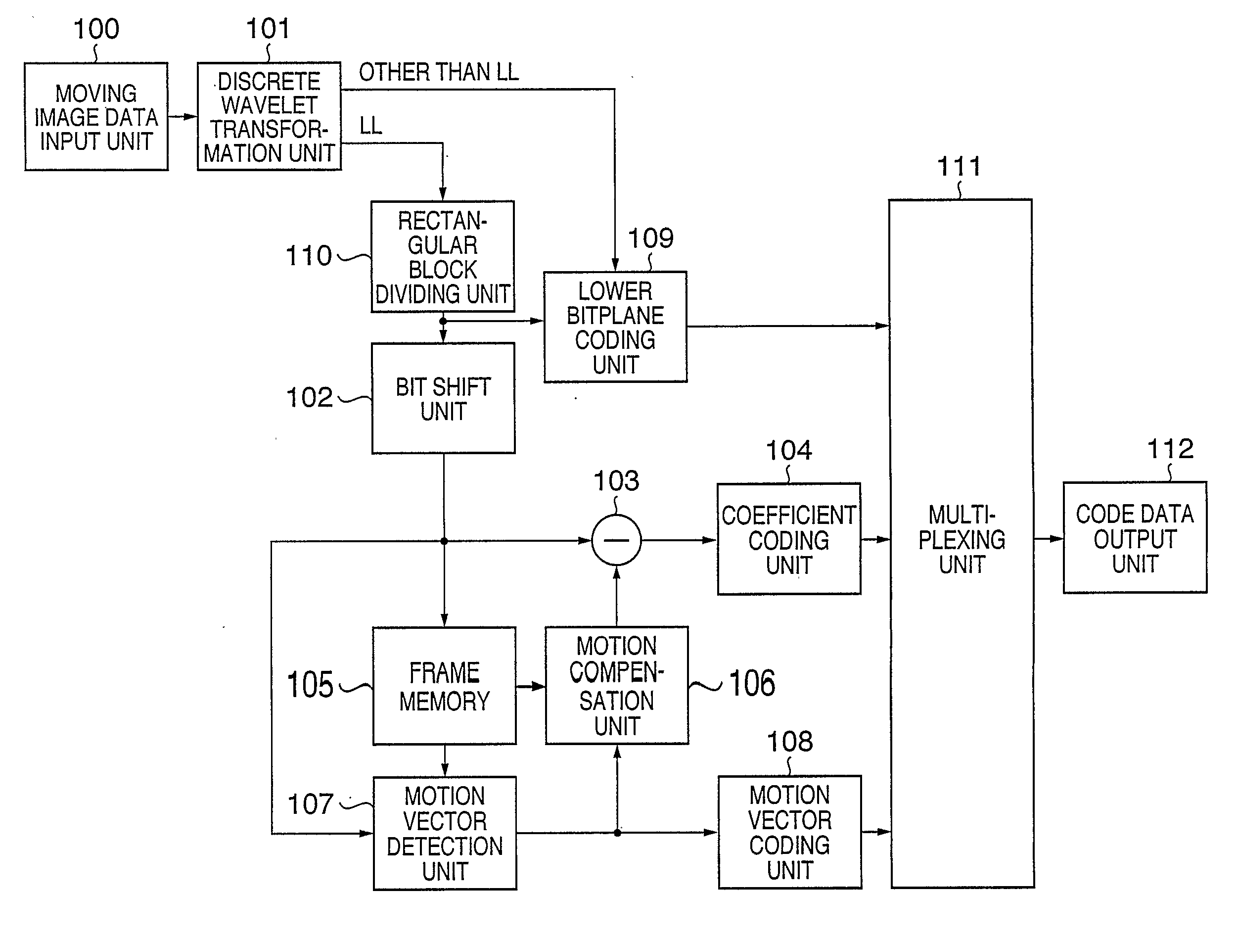
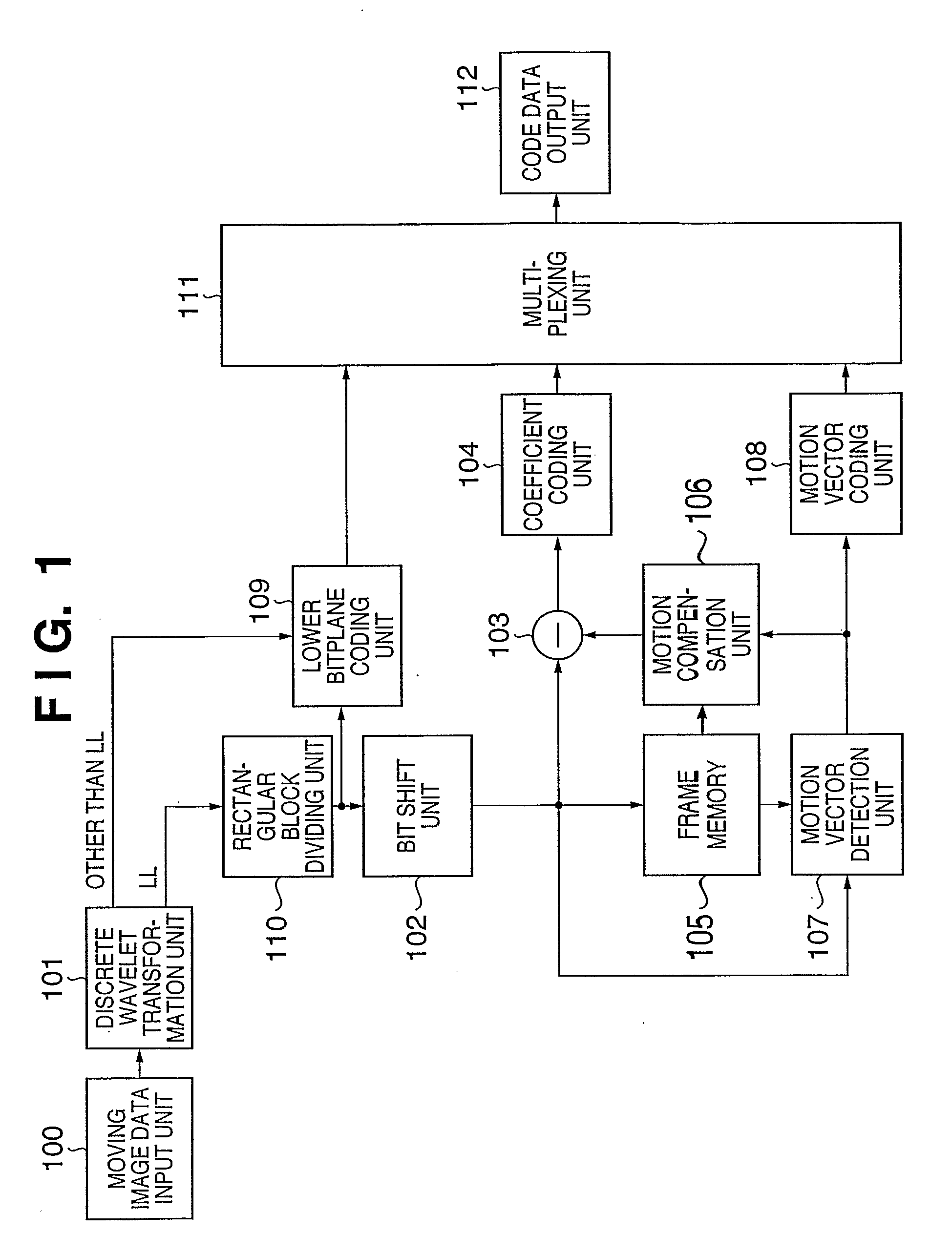
[0055]FIG. 1 is a block diagram showing the arrangement of a moving image coding apparatus according to the first embodiment. Referring to FIG. 1, reference numeral 100 denotes a moving image data input unit; 101, a discrete wavelet transformation unit; 102, a bit shift unit; 103, a subtracter; 104, a coefficient coding unit; 105, a frame memory; 106, a motion compensation unit; 107, a motion vector detection unit; 108, a motion vector coding unit; 109, lower bitplane coding unit; 110, a rectangular block dividing unit; 111, a multiplexing unit; and 112, a code data output unit.

[0056] The operation of each constituent element of the moving image coding apparatus shown in FIG. 1 will be described next. Assume that the input frame rate of the moving image data input unit 100 is 30 frames / sec, and the image of each frame is monochrome moving image data with each pixel having a luminance value of eight bits. Assume that the data of such a moving image is captured in th...

Example

Second Embodiment

[0122] The first embodiment has exemplified the arrangement in which motion compensation is applied to only the upper bit portion of the subband LL. As described above, however, motion compensation may be applied to the upper bit portions of subbands other than the subband LL. In addition, in wavelet transformation, a lossless filter of an integer arithmetic type is used. If, however, lossless coding is not required, a real type filter may be used, and various kinds of quantization techniques can be used.

[0123] The second embodiment will exemplify an arrangement which applies motion compensation to all subbands and uses a real type filter and quantization.

[0124]FIG. 7 is a block diagram showing the arrangement of a moving image coding apparatus according to the second embodiment.

[0125] The same reference numerals as in FIG. 7 denote parts having the same functions as those in the first embodiment in FIG. 1 described above, and a description thereof will be omitt...

Example

Third Embodiment

[0166] Although there has been no mention about the adjustment of the overall code amount of moving image code data to be output in the moving image coding apparatuses according to the first and second embodiments described above, the generated code amount can be easily controlled by adjusting the range of lower bitplanes to be coded. The third embodiment will exemplify a case wherein an overall code amount is adjusted.

[0167]FIG. 11 is a block diagram showing the arrangement of a moving image coding apparatus according to the third embodiment. The moving image coding apparatus of the third embodiment has an arrangement obtained by adding a non-coding bitplane decision unit 1101 to the moving image coding apparatus of the second embodiment shown in FIG. 7. Differences in operation from the moving image coding apparatus of the second embodiment will be described below.

[0168] A lower bitplane coding unit 109 codes the lower Tb bits of each subband as in the moving im...


PUM


Abstract

This invention provides a technique of preventing errors from being gradually accumulated on the decoding side, while maintaining high scalability, even when a technique for transformation to subbands as a plurality of frequency components, like discrete wavelet transformation, is used for moving image coding. The image data of one input frame is decomposed into a plurality of subbands having different frequency components by a discrete wavelet transformation unit (101). A lower bitplane coding unit (109) codes, for each bitplane, predetermined lower bits of each coefficient data of a subband LL and the coefficient data of subbands other than the subband LL. The data of the upper bits of the subband LL is stored in a frame memory (105). A motion vector detection unit (107) detects a predicted value and motion vector on the basis of the decoded data of the subband LL in a preceding frame. A subtracter (103) obtains the difference between the detected predicted value and the current frame. A coefficient coding unit (104) codes the obtained difference. A motion vector coding unit (108) codes the motion vector. A multiplexing unit (111) multiplexes the code data obtained by the coding units (104, 108, 109).

Description

TECHNICAL FIELD [0001] The present invention relates to a compression coding technique and decoding technique for moving images. BACKGROUND ART [0002] Recently, contents flowing through networks have increased in volume and diversity from character information to still image information, further to moving image information. Accordingly, coding techniques for compressing information amounts have been developed. The developed coding techniques Save been standardized internationally and widely spread. [0003] On the other hand, networks themselves have increased capacity and diversity, and hence one content from the transmitting side passes through various environments until it reaches the receiving side. In addition, transmitting / receiving-side devices have diversified in terms of processing performance. General-purpose information processing apparatuses such as personal computers (to be referred to as PCs hereinafter) mainly used as transmission / reception devices have exhibited great ...

Claims


Application Information

Patent Timeline
IPC IPC(8): G06K9/46H04N19/50H04N19/33H04N19/34H04N19/46H04N19/463H04N19/517H04N19/60H04N19/625H04N19/63H04N19/70H04N19/91
CPCH04N19/46H04N19/63H04N19/169H04N19/64H04N19/17H04N19/184H04N19/61
Inventor KAJIWARA, HIROSHIMAEDA, MITSURUSUZUKI, MASAKIKISHI, HIROKI
Owner CANON KK
Why Eureka
Try Eureka