Hole cutter having detachable hole-sawing blade

a hole cutter and hole-sawing technology, which is applied in the field of hole cutters, can solve the problems of a large amount of time and insufficient function of the design of the hole cutter, and achieve the effect of quick replacemen

Inactive Publication Date: 2007-07-12
CHAO WALLEY
View PDF17 Cites 40 Cited by
  • Summary
  • Abstract
  • Description
  • Claims
  • Application Information

AI Technical Summary

Benefits of technology

[0005] The present invention has been accomplished under the circumstances in view. It is one object of the pre

Problems solved by technology

However, this design of hole cutter is still not satisfactory in function.
When cutting a dif

Method used


Image

  • Hole cutter having detachable hole-sawing blade
  • Hole cutter having detachable hole-sawing blade
  • Hole cutter having detachable hole-sawing blade

Examples


Embodiment Construction

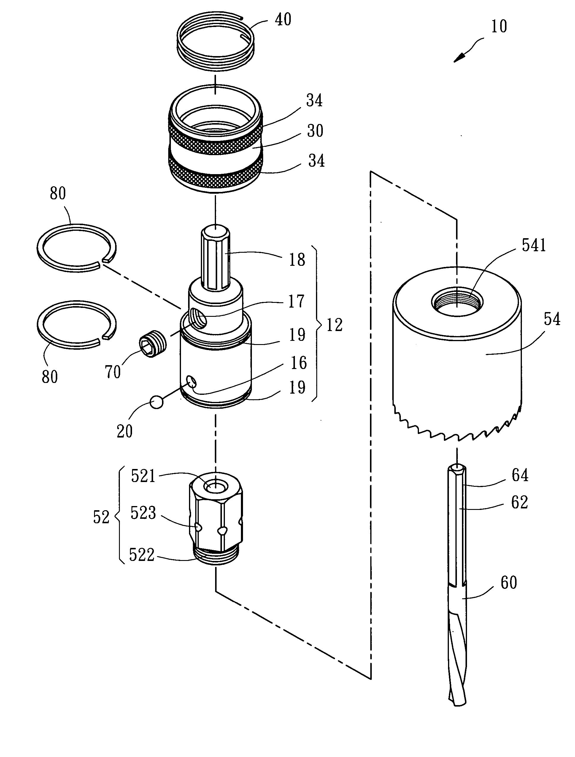
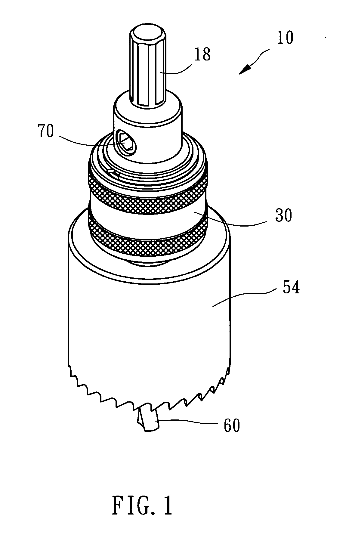
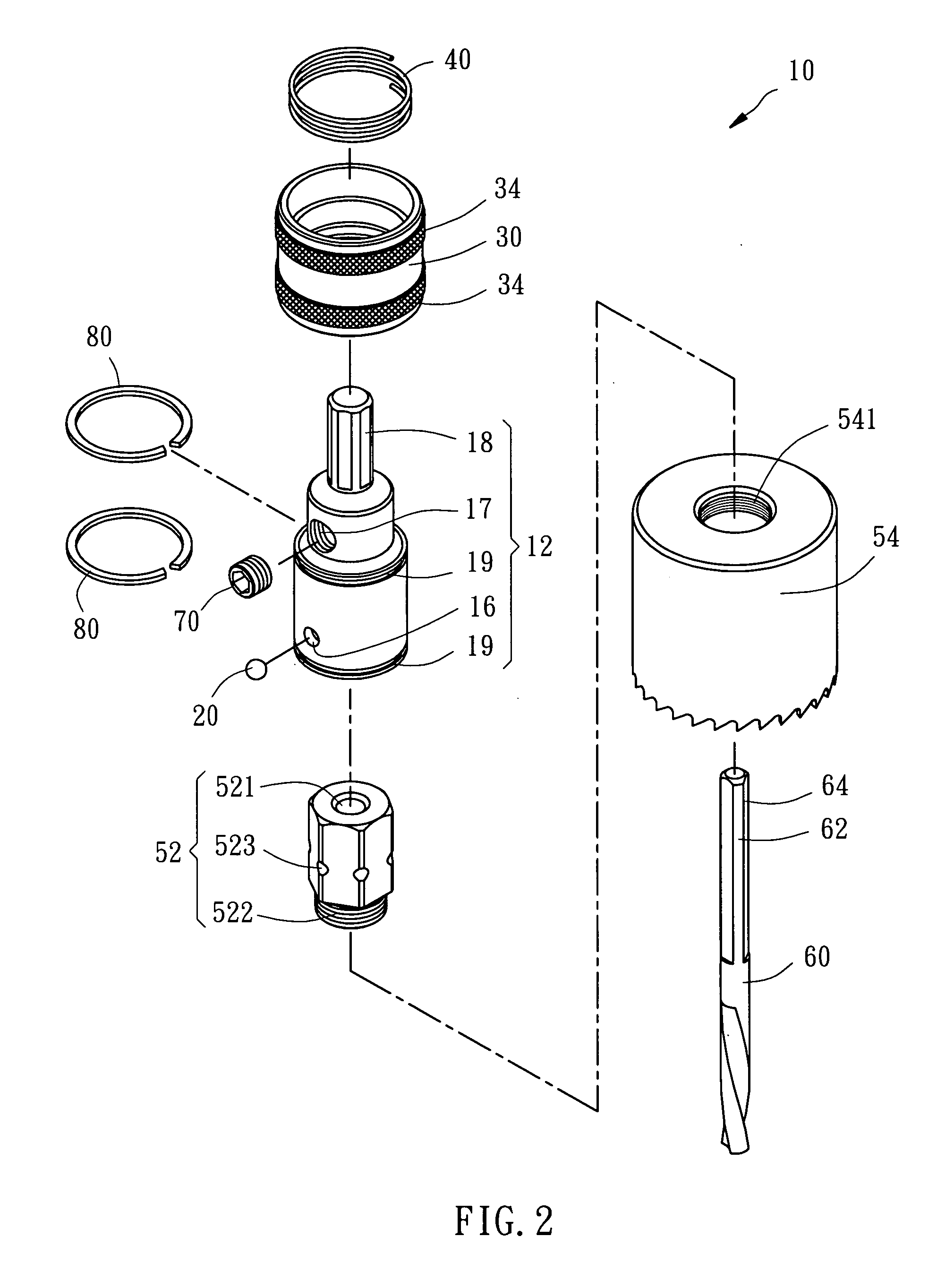
[0012] Referring to FIGS. 1-4, a hole cutter 10 in accordance with a preferred embodiment of the present invention is shown comprising a shaft 12, a steel ball 20, a socket 30, a spring member 40, a hole-sawing blade assembly 50, a drill bit 60, a screw rod 70, and retaining members 80.

[0013] The shaft 12 is a stepped cylindrical member having a bottom open chamber 14, which has a hexagonal cross section, an inside hole 15 axially extending from a bottom of the bottom open chamber 14 towards a top side of the shaft, a locating hole 16 transversely extending from one side of the bottom open chamber 14 to the outer periphery of the shaft 12, a screw hole 17 transversely extending from one side of the inside hole 15 to the periphery of the shaft 12, a top coupling portion 18 axially disposed at the top side remote from the bottom open chamber 14 and connectable to a rotary driving tool (not shown), and two locating grooves 19 extending around the outer periphery of the shaft 12 at dif...


PUM


Abstract

A hole cutter includes a shaft connectable to a rotary driving tool, a ball mounted in a locating hole of the shaft, a detachable hole-sawing blade assembly detachably inserted into a bottom open chamber of the shaft, a socket supported on a spring member provided at the shaft to force the ball to lock the detachable hole-sawing blade assembly, and a drill bit inserted through the detachable hole-sawing blade assembly into the inside of the shaft and locked by a screw rod.

Description

BACKGROUND OF THE INVENTION [0001] 1. Field of the Invention [0002] The present invention relates to a hole cutter for sawing a circular hole and more particularly, to a hole cutter having a hold-sawing blade that is detachable and can be replaced quickly. [0003] 2. Description of the Related Art [0004] A conventional hole cutter is known using two knife blades to cut the workpiece through a rotary motion. Taiwan patent publication No. M244141 discloses a similar design. According to this design, the hole cutter comprises a holder base, a drill bit, a rod scale, two sliding blocks, two knife blades, a dust cap, and a quick-release connector. The quick-release connector connects the hole cutter to a rotary driving tool so that the two knife blades are rotatable with the rotary driving tool to cut the workpiece. However, this design of hole cutter is still not satisfactory in function. When one knife blade is damaged or starts to wear, the whole assembly must be disassembled so that t...

Claims


Application Information

Patent Timeline
IPC IPC(8): B23B39/00B23B51/04
CPCB23B31/1071Y10T408/895Y10T408/5628B23B51/0473
Inventor CHAO, WALLEY
Owner CHAO WALLEY
Why Eureka
Try Eureka