Methods, systems, and computer program products for providing dynamic data of positional localization of target implants

a technology for implanted devices and positional localization, applied in diagnostic recording/measuring, applications, therapy, etc., can solve problems such as complex delivery of external beam radiation doses in the desired dose amount to the actual tumor site, and increase the potential for collateral damage to healthy or non-targeted tissu

Inactive Publication Date: 2007-07-12
VTQ IP HLDG
View PDF40 Cites 48 Cited by
  • Summary
  • Abstract
  • Description
  • Claims
  • Application Information

AI Technical Summary

Benefits of technology

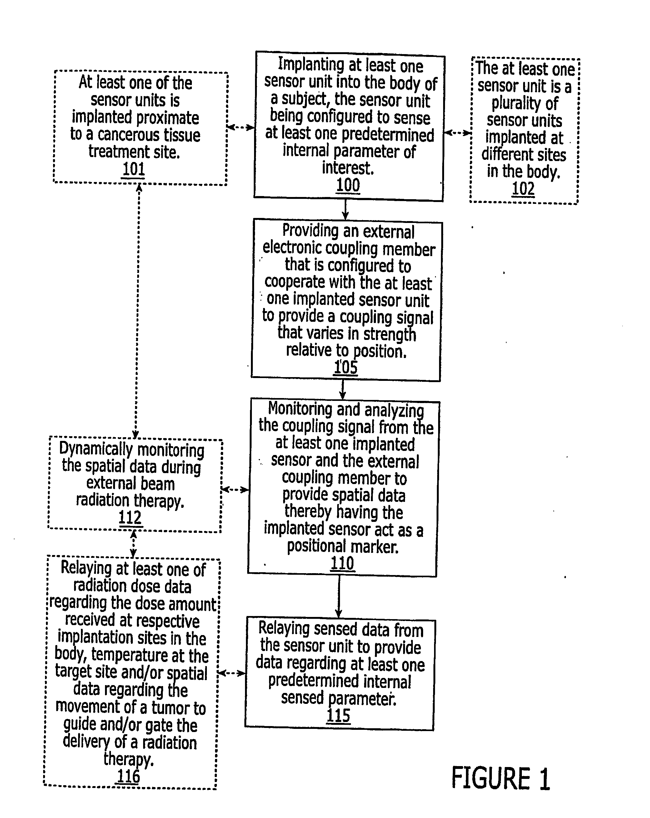
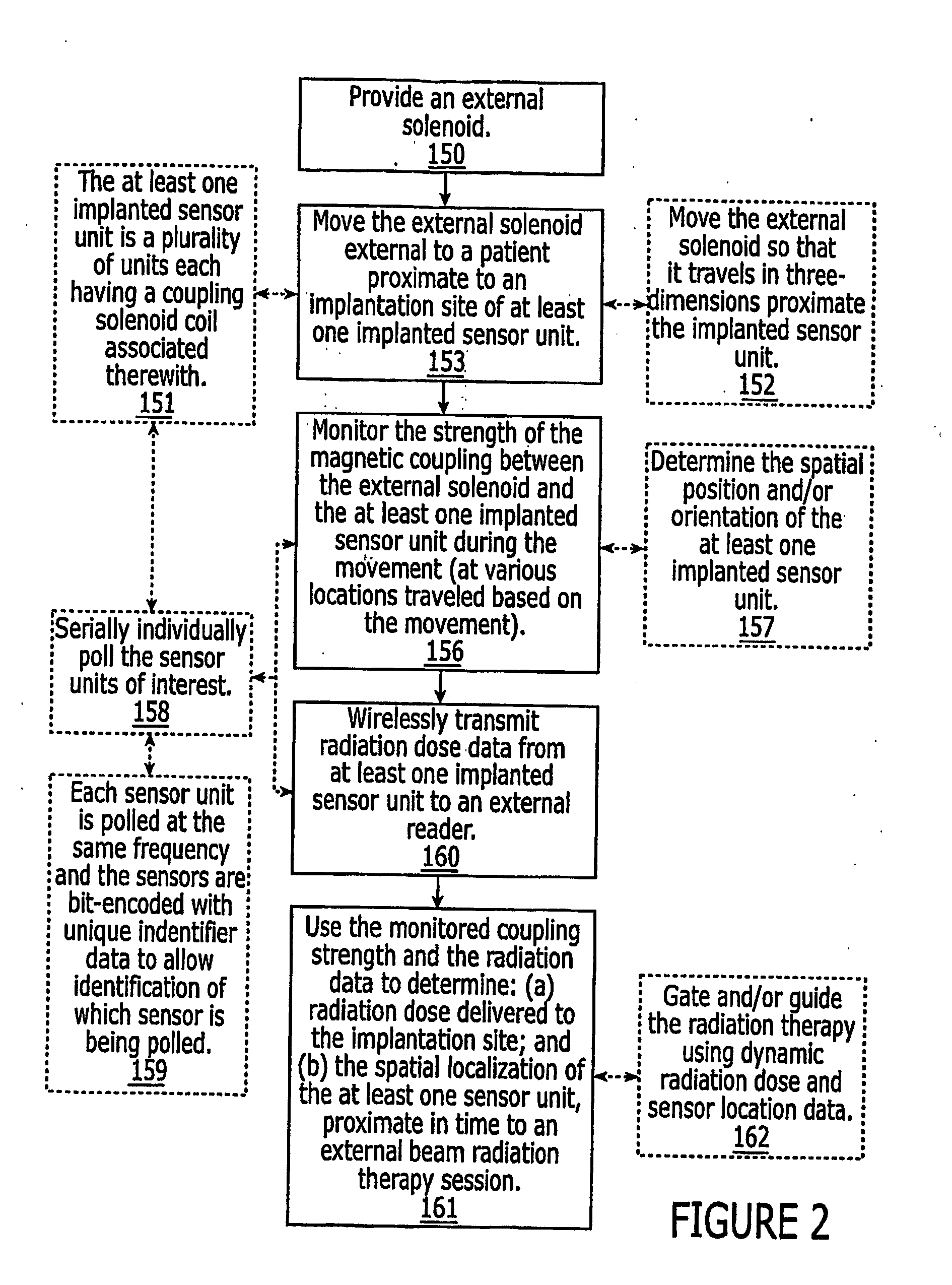
[0018] Other embodiments of the present invention are directed to methods of obtaining spatial data and radiation dose data regarding a target in vivo treatment site. The methods include: (a) implanting at least one sensor unit proximate and / or in a target treatment site of a patient; (b) sensing in vivo at least one predetermined parameter of interest using the implanted sensor unit; (c) wirelessly transmitting data associated with the sensed at least one parameter from the at least one sensor unit to an external reader; (d) providing an external coupling member located external of the patient proximate the target treatment site, the coupling member being configured to cooperate with the at least one implanted sensor to generate a coupling signal that varies in relation to the position of the coupling member with respect to the at least one sensor unit; (e) moving the coupling member; (f) detecting the signal strength of the coupling signal at a plurality of locations traveled based on the moving step; and (g) determining the position of the at least one sensor unit in the body based on the detecting step, thereby having the implanted sensor unit act as a positional marker and an in vivo sensor.
[0019] In particular embodiments, the method can also include: positioning the patient in an imaging system in a registered position; obtaining an image of the target treatment site and at least one implanted sensor with the patient in the registered position in an imaging system; aligning the coupling member to a fiducial marker on the imaging system relative to the registered position; and obtaining an electrical measurement of signal strength of the coupling signal while the patient is in the registered position and the coupling member is aligned to define the initial spatial position of the at least one sensor unit in three-dimensional space.
[0020] Other embodiments are directed toward computer program products for obtaining spatial data regarding the position of at least one implanted sensor. The program includes: computer readable storage medium having computer readable program code embodied in the medium, the computer-readable program code comprising computer readable program code for determining the spatial location of a selected one of the at least one implanted sensor units using input data associated with variation in signal strength of a coupling signal generated by an external solenoid and the at least one sensor unit over different known external positions of the external solenoid.

Problems solved by technology

The variation can be particularly problematic when radiation therapy is used on deep tumors, when the therapy is delivered to tumors located close to healthy sensitive regions or organs, and / or when complex beam signals are employed.
However, delivering external beam radiation doses in the desired dose amount to the actual tumor site can be complicated as the tumor and / or markers used to locate and guide the radiation therapy may shift over time, either during or between radiation sessions.
Thus, dynamic changes in the position of the tumor during active radiation delivery can increase the potential of collateral damage to healthy or non-targeted tissue.

Method used


Image

  • Methods, systems, and computer program products for providing dynamic data of positional localization of target implants
  • Methods, systems, and computer program products for providing dynamic data of positional localization of target implants
  • Methods, systems, and computer program products for providing dynamic data of positional localization of target implants

Examples


examples

[0083] Empirical measurements were taken with an implantable sensor unit having an 10 internal coil positioned at different orientations and coupling distances away from an external solenoid coil. The experimental set-up is shown in FIG. 8 and a typical probe-response set of waveforms (coupling signals) is shown in FIG. 9. As shown in FIG. 8, a ruler 76R was laid on a table-top surface 76T for positional reference. A first measurement was taken with the external and sensor coils parallel to each other with the sensor unit coil being positioned approximately centrally of the external larger coil. In this orientation, the coupling is maximal when the sensor coil is substantially centered in this manner. FIG. 10 illustrates the relationship between separation distance (cm) and induced voltage (mV). FIG. 9 illustrates an applied signal (from the external solenoid) and a response (coupling) signal. The applied voltage is the larger amplitude wave signal and the response or coupling signa...


PUM


Abstract

Systems for locating implanted in vivo sensors systems adapted for use with an external beam radiation therapy delivery source include: (a) an external solenoid member; (b) an articulated arm opertively associated with the external solenoid member, wherein, in operation, the articulated arm is configured to translate the solenoid; (c) a controller configured to direct the movement of the articulated arm, the controller being in communication with the power source configured to power the external solenoid; (d) at least one implantable sensors unit, wherein the at least one implantable sensor unit is configured to sense at least one predetermined parameter of interest in vivo, and wherein the at least one implantable sensor unit comprises a solenoid, and wherein, in operation, the sensor unit solenoid corporates with the external solenoid to generate a magnetic coupling signal having a signal strength that varies based on the possession of the external solenoid member relative to the implanted sensors unit; (e) a computer module in communication with the controller comprising computer programmed code that evaluates the coupling signal strength in relation to the position of the external solenoid and determines the position of the at least one sensor unit; and (f) an external reader configured to wirelessly communicate with the at least one implantable sensor unit to obtain data associated with the at least one predetermined parameter of interest.

Description

RELATED APPLICATIONS [0001] This application claims the benefit of priority of U.S. Provisional Patent Application No. 60 / 459,697, filed Apr. 2, 2003, the contents of which are hereby incorporated by reference as if recited in fill herein.FIELD OF THE INVENTION [0002] This invention relates to systems for determining the location of implanted devices. BACKGROUND OF THE INVENTION [0003] Radiation therapy is used to treat localized cancers or other conditions. Examples of radiation therapy treatments include conventional external beam radiation therapy, as well as three-dimensional conformal external beam radiation, intensity modulated radiation therapy (IMRT), a “gamma knife” that employs a highly focused gamma ray radiation obtained from crossing or collimating several radiation beams, stereotactic radiosurgery and brachytherapy. [0004] The efficacy of the radiation treatment can depend on the total dose of radiation delivered to the target region. However, the amount of radiation e...

Claims


Application Information

Patent Timeline
Patent Type & Authority Applications(United States)
IPC IPC(8): A61B5/05A61B5/00A61B5/06A61B19/00A61N5/10G06F
CPCA61B5/0008A61N2005/1051A61B5/06A61B19/5225A61B19/5244A61B2017/00022A61B2017/00411A61B2019/448A61B2019/507A61B2019/5251A61B2019/5272A61B2019/547A61B2019/5475A61N5/1048A61B5/0031A61B5/062A61B34/20A61B90/37A61B90/98A61B2034/107A61B2034/2051A61B2034/2072A61B2090/397A61B2090/3975
Inventor BLACK, ROBERT D.MANN, GREGORY GLENWOODWIDENER, STEVEN R.
Owner VTQ IP HLDG
Why Eureka
Try Eureka