Fan speed control methods

a technology of speed control and fan, applied in the direction of electric controllers, ignition automatic control, instruments, etc., can solve problems such as reducing efficiency, and achieve the effect of discharging heat from electric devices

Inactive Publication Date: 2007-07-12
GIGA BYTE TECH CO LTD
View PDF6 Cites 32 Cited by
  • Summary
  • Abstract
  • Description
  • Claims
  • Application Information

AI Technical Summary

Benefits of technology

[0006]Fan speed control methods are provided to dissipate heat from an electric device in a computer system. A load-temperature curve of the electronic device is determined by detecting load and temperature th

Problems solved by technology

Since high temperatures can reduce efficiency, cooling fans are c

Method used


Image

  • Fan speed control methods
  • Fan speed control methods
  • Fan speed control methods

Examples


Embodiment Construction

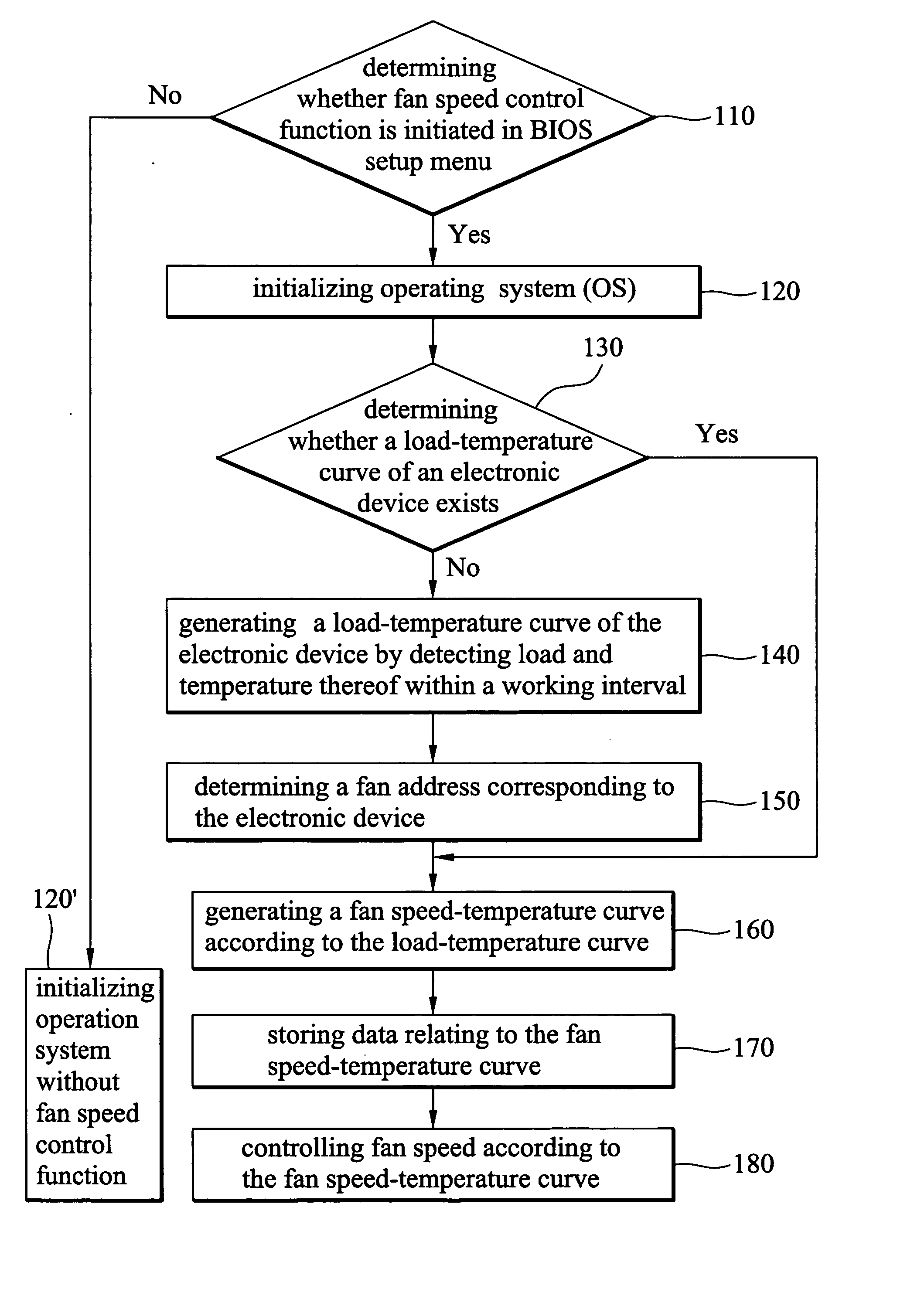
[0016]FIG. 5 shows an embodiment of a method of fan speed control, to dissipate heat from an electronic device. The electronic device can be a CPU, IC, motherboard, or power supply of a computer.

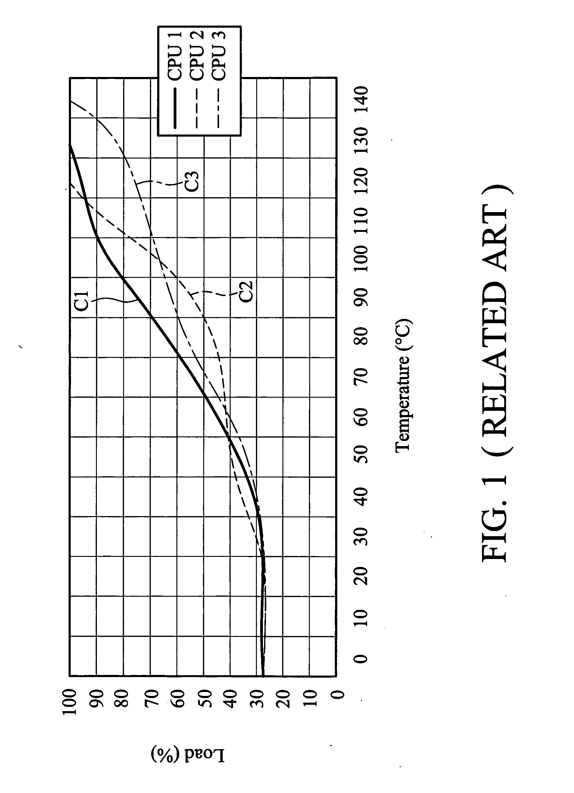
[0017]As shown in FIG. 5, from a BIOS (Basic Input Output System) setup menu, a fan speed control mode can be defined to initiate a fan speed control function (step 110) and initialize an operating system (step 120), or directly initialize an operating system without fan speed control (step 120′). Once the fan speed control function is initiated in BIOS setup menu, in step 130, it is determined whether a load-temperature curve corresponding to an electronic device exists in the operating system. An exemplary embodiment of the load-temperature curve is depicted in FIG. 6, wherein Lmax and Lmin represent maximum and minimum loads of the electronic device within a working interval, and Tmax and Tmin represent maximum and minimum temperatures thereof within the working interval.

[0018]If the load...


PUM


Abstract

Fan speed control methods are provided to dissipate heat from an electric device in a computer system. A load-temperature curve of the electronic device is determined by detecting load and temperature thereof within a working interval. Subsequently, a fan speed-temperature curve is determined according to the load-temperature curve, and the fan speed is controlled according to the fan speed-temperature curve.

Description

BACKGROUND OF THE INVENTION[0001]1. Field of the Invention[0002]The invention relates in general to fan speed control, and in particular to fan speed control methods for computers.[0003]2. Description of the Related Art[0004]Conventional computers comprise many electronic devices generating heat, such as power supplies, motherboards, and CPUs, having individual load-temperature curves. As shown in FIG. 1, three load-temperature curves C1, C2 and C3 of three CPUs CPU1, CPU2 and CPU3 are distinct from each other due to individual function and electrical properties.[0005]Since high temperatures can reduce efficiency, cooling fans are conventionally provided to dissipate heat from responsible devices. Conventional cooling fans are controlled according to predetermined fan speed-temperature curves, as shown in FIGS. 2, 3, and 4, wherein the fan speed-temperature curves are fixed. In FIG. 2, the fan speed is constant regardless of temperature variation. The fan speed-temperature curve may...

Claims


Application Information

Patent Timeline
IPC IPC(8): G05B11/01
CPCY02B60/1275G06F1/206Y02D10/00
Inventor CHANG, AN-SHENGTSAI, LIEN-CHANGHUANG, SHUN-CHIH
Owner GIGA BYTE TECH CO LTD
Why Eureka
Try Eureka