System and method for cooling a staged airblast fuel injector

a fuel injector and staged technology, applied in the field of fuel injection, can solve the problems of degrading engine performance, unable to protect against carbon formation, and stagnant fuel located within the main fuel circuit,

Active Publication Date: 2007-07-19
ROLLS ROYCE PLC
View PDF10 Cites 73 Cited by
  • Summary
  • Abstract
  • Description
  • Claims
  • Application Information

AI Technical Summary

Benefits of technology

[0008] In accordance with the subject invention, the pilot fuel circuit is in thermal contact with the main fuel circuit, enroute to the pilot fuel atomizer. In doing so, the pilot fuel flowing through the pilot fuel circuit cools or otherwise protects the main fuel circuit from carbon formation during low power operation, when the there is typically stagnant fuel located in the main fuel circuit. In addition, the close proximity of the main and pilot fuel circuits within the main fuel atomizer enables the main fuel flow to cool the pilot fuel flow when the engine is operating at high power and fuel is flowing in both circuits.
[0011] The main fuel circuit includes a plurality of circumferentially spaced apart angled fuel exit slots, which are formed in the outer diametrical surface of the fuel swirler and feed into an annular main fuel spin chamber. In accordance with a preferred embodiment of the subject invention, the pilot fuel circuit is located in close proximity to the fuel exit slots of the main fuel circuit, so that the pilot fuel circuit forms a cooling channel around the main fuel circuit. Preferably, the spin chamber is configured as a self-draining spin chamber so that it is not necessary to route the pilot cooling circuit in proximity thereto.

Problems solved by technology

One difficulty associated with operating a staged fuel injector is that when the pilot fuel circuit is operating alone during low power operation, stagnant fuel located within the main fuel circuit can be susceptible to carbon formation or coking due to the temperatures associated with the operating environment.
This can degrade engine performance over time.
To date however, active cooling has not been used to protect against carbon formation in the main fuel circuit of a staged airblast fuel injector.

Method used


Image

  • System and method for cooling a staged airblast fuel injector
  • System and method for cooling a staged airblast fuel injector
  • System and method for cooling a staged airblast fuel injector

Examples


Embodiment Construction

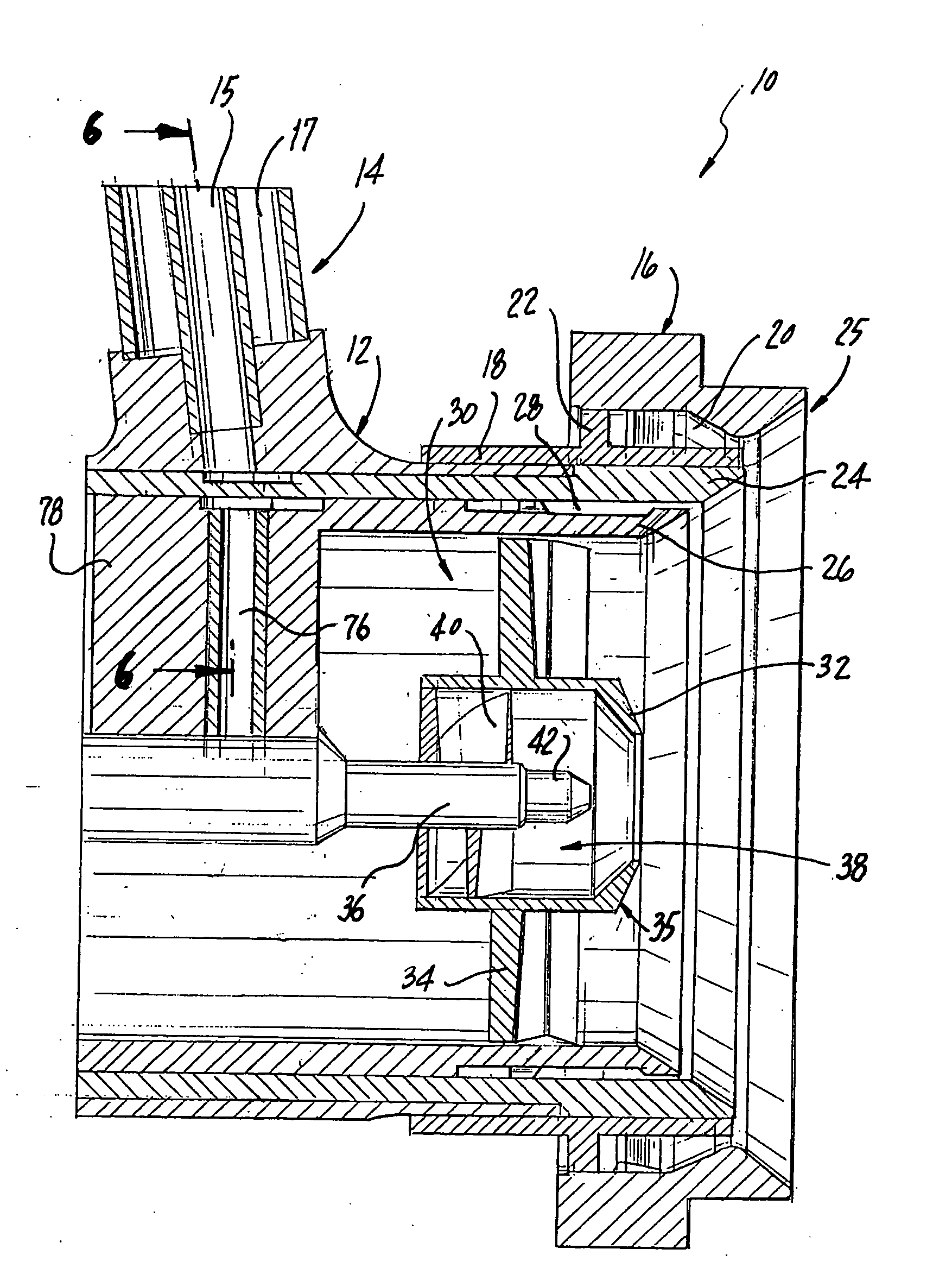
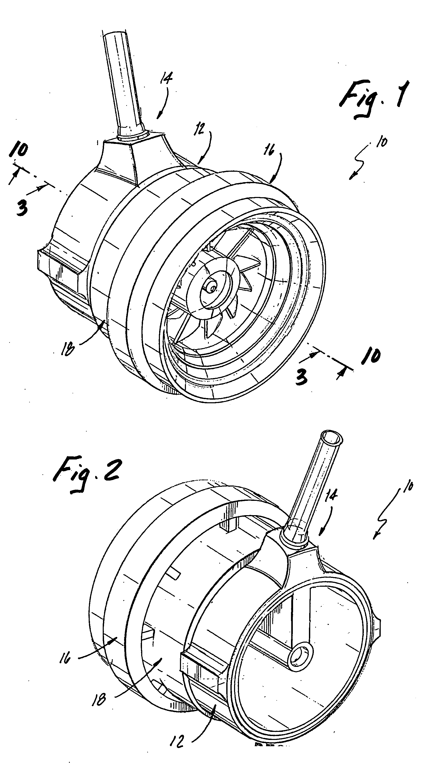
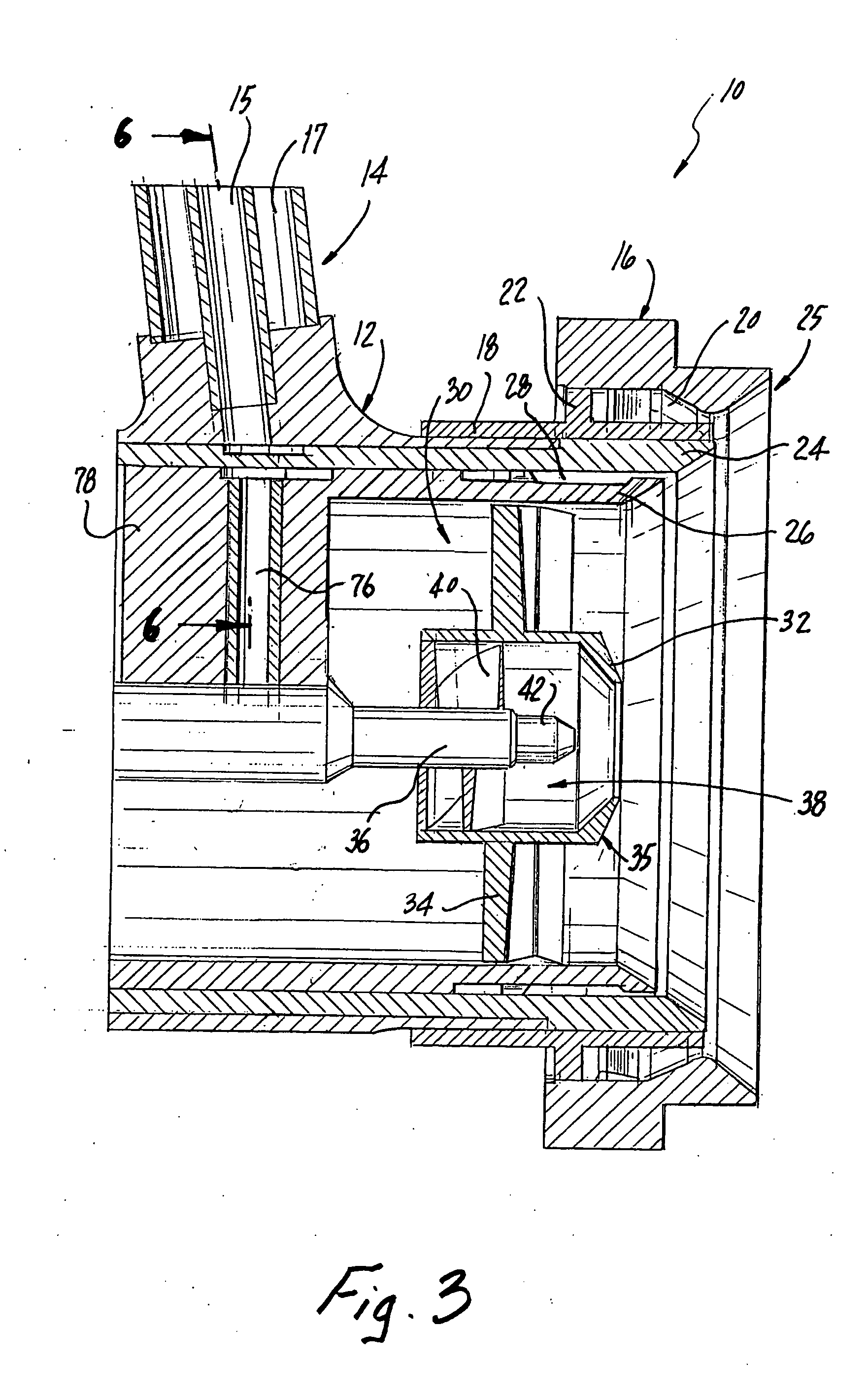
[0029] Referring now to the drawings wherein like reference numerals identify similar structural features or aspects of the subject invention, there is illustrated in FIG. 1 a fuel injector constructed in accordance with a preferred embodiment of the subject invention and designated generally by reference numeral 10. Fuel injector 10 is adapted and configured for delivering fuel to the combustion chamber of a gas turbine engine. Fuel injector 10 is generally referred to as a staged fuel injector in that it includes a pilot fuel circuit, which typically operates during engine ignition and at low engine power and a main fuel circuit, which typically operates at high engine power (e.g., at take-off and cruise) and is typically staged off at lower power operation.

[0030] Referring to FIG. 1, fuel injector 10 includes a generally cylindrical nozzle body 12, which depends from an elongated feed arm 14. In operation, main and pilot fuel is delivered into nozzle body 12 through concentric f...


PUM


Abstract

A staged fuel injector is disclosed that includes a main fuel circuit for delivering fuel to a main fuel atomizer and a pilot fuel circuit for delivering fuel to a pilot fuel atomizer located radially inward of the main fuel atomizer. The pilot fuel circuit is in close proximity to the main fuel circuit enroute to the pilot fuel atomizer so that the pilot fuel flow cools stagnant fuel located within the main fuel circuit during low engine power operation to prevent coking.

Description

BACKGROUND OF THE INVENTION [0001] 1. Field of the Invention [0002] The subject invention is directed to fuel injection, and more particularly, to a system and method for cooling the exit slots of the main fuel circuit of a staged airblast fuel injector using the pilot fuel flow, at low engine power. [0003] 2. Background of the Related Art [0004] Staged fuel injectors for gas turbine engines are well know in the art. They typically include a pilot fuel atomizer for use during engine ignition and low power engine operation and at least one main fuel atomizer for use during high power engine operation in concert with the pilot fuel atomizer. One difficulty associated with operating a staged fuel injector is that when the pilot fuel circuit is operating alone during low power operation, stagnant fuel located within the main fuel circuit can be susceptible to carbon formation or coking due to the temperatures associated with the operating environment. This can degrade engine performance...

Claims


Application Information

Patent Timeline
Patent Type & Authority Applications(United States)
IPC IPC(8): F02C7/22
CPCF23D2900/11101F23R3/283F23R3/343F23D11/36F23R3/346
Inventor THOMSON, NEAL
Owner ROLLS ROYCE PLC
Why Eureka
Try Eureka