Image display and electronic device

a technology of electronic devices and images, applied in optics, instruments, electrical devices, etc., can solve problems such as image darkness

Active Publication Date: 2007-07-19
JAPAN DISPLAY WEST
View PDF4 Cites 22 Cited by
  • Summary
  • Abstract
  • Description
  • Claims
  • Application Information

AI Technical Summary

Benefits of technology

[0016]According to those aspects of the invention, dual-view display can be performed without reducing the brightness of an image viewed by each viewer.

Problems solved by technology

Unfortunately, the image appears dark.

Method used


Image

  • Image display and electronic device
  • Image display and electronic device
  • Image display and electronic device

Examples


Embodiment Construction

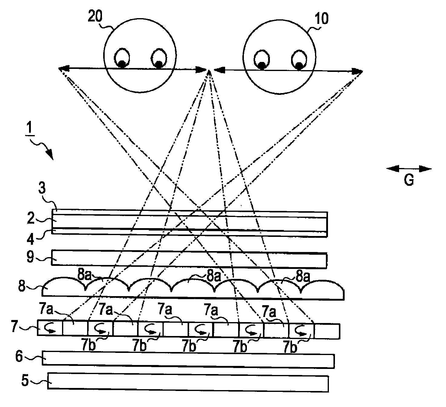
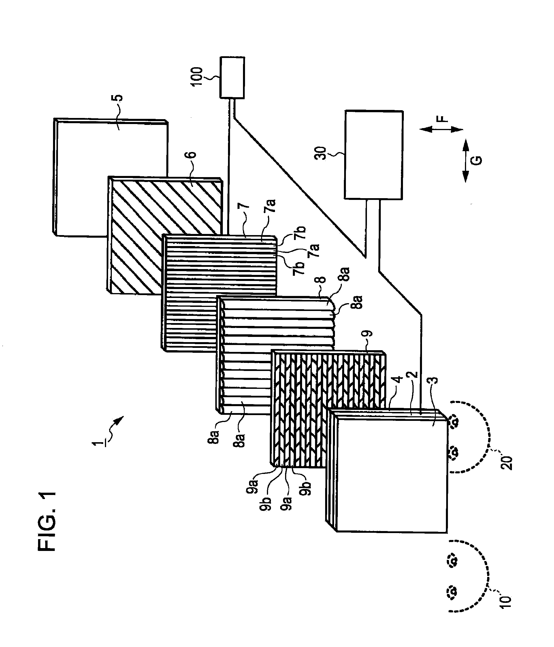
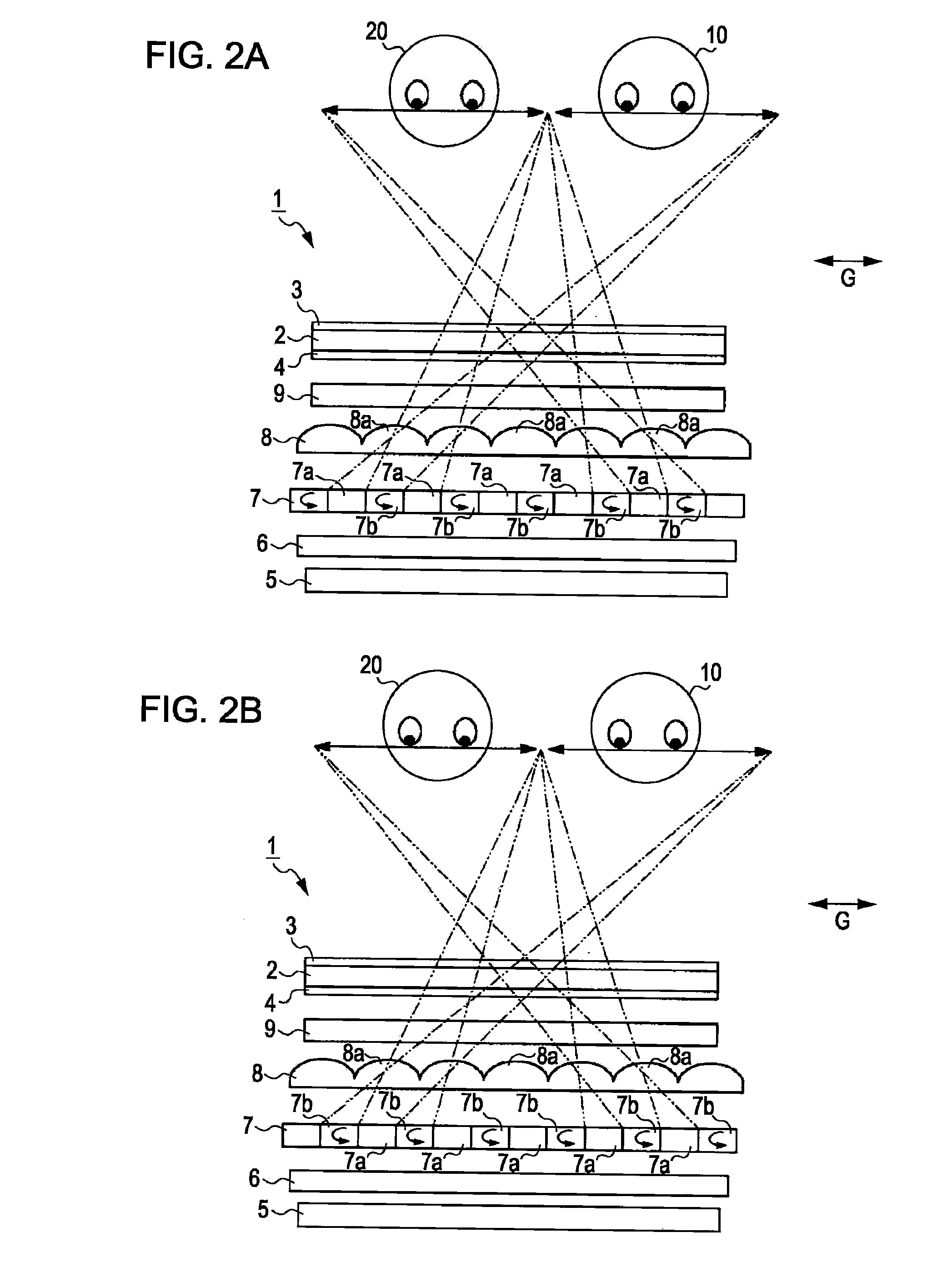
[0030]Embodiments of the invention will be described below with reference to the drawings. FIG. 1 is an exploded perspective view of an image display according to an embodiment of the invention. FIGS. 2A and 2B are diagrams showing states where viewers located in front of the image display view a display panel, the diagrams explaining the principle of the image display. FIG. 3 is a partially enlarged view of a polarization control liquid crystal panel of the image display shown in FIG. 1.

[0031]Referring to FIG. 1, an image display 1 according to the present embodiment presents different images L2 and R2 to different viewers 10 and 20 located in different viewing positions. Hereinafter, such a state of the image display 1 will be called a dual-view display mode. The image display 1 according to this embodiment has a first dual-view display mode and a second dual-view display mode. In the first dual-view display mode, the image display 1 presents the image L2 to the viewer 10 and simu...


PUM


Abstract

An image display includes the following components. A display panel has a plurality of pixels arrayed in a first direction and a second direction intersecting the first direction. A light source emits light toward the display panel. A polarization-axis control unit is disposed between the display panel and the light source. The polarization-axis control unit separates the light emitted from the light source into light having a first polarization axis and light having a second polarization axis different from the first polarization axis. An optical element is arranged between the display panel and the polarization-axis control unit. The optical element allows the light emitted from the light source to travel in a direction substantially orthogonal to the first direction. The polarization-axis control unit includes a first substrate, a second substrate, a liquid crystal layer sandwiched between the first and second substrates, a plurality of first electrodes extending in the first direction arranged at a predetermined pitch in the second direction on the first substrate, and a second electrode on the second substrate. The first electrodes each having a connecting part and a plurality of strip electrode segments extending from the connecting part are arranged in such a manner that the respective connecting parts are arranged in opposite end portions of the first substrate and the strip electrode segments are alternately arranged over a surface of the first substrate. The second electrode is superposed over the first electrodes in a region corresponding to a pixel array area of the display panel.

Description

BACKGROUND[0001]1. Technical Field[0002]The present invention relates to image displays and electronic devices, and in particular, relates to an image display having a polarization-axis control unit and an electronic device having the image display.[0003]2. Related Art[0004]As one of image displays for displaying a three-dimensional stereoscopic image, a three-dimensional image display disclosed in Japanese Patent No. 2,857,429 is known. In this three-dimensional image display, a controller, such as a microcomputer, controls an electronic parallax barrier disposed on one side of a screen facing to a viewer to form light-transmitting portions and light-shielding portions in the parallax barrier so that the viewer sees left-eye and right-eye images with their left and right eyes, respectively.[0005]In other words, the image display using the parallax barrier presents different images to the left and right eyes of the viewer, thus allowing the viewer to perceive the different images as...

Claims


Application Information

Patent Timeline
Patent Type & Authority Applications(United States)
IPC IPC(8): G09G3/36G02B30/30
CPCG02B27/225G09G3/3406H04N13/0418H04N13/0404H04N13/0497G09G2340/145H04N13/305H04N13/32H04N13/398G02B30/30
Inventor TAJIRI, KENICHI
Owner JAPAN DISPLAY WEST
Why Eureka
Try Eureka