Liquid crystal display device and head-up display using it

a display device and liquid crystal technology, applied in static indicating devices, instruments, optics, etc., can solve the problems of increasing the brightness of the frame body, increasing the cost as well as the size of the head-up display, and unable to form virtual images, etc., to achieve rapid rise in the temperature of the liquid crystal cell, facilitate conduction of heat, and increase the thermal conductivity of the frame

Inactive Publication Date: 2007-07-19
EPSON IMAGING DEVICES CORP
View PDF6 Cites 14 Cited by
  • Summary
  • Abstract
  • Description
  • Claims
  • Application Information

AI Technical Summary

Benefits of technology

[0022] Preferably, in the head-up display described above, the liquid crystal display device further includes a flexible printed circuit board that is connected, at one end thereof, near an edge of the liquid crystal cell and is exposed, at the other end thereof, outside of the frame body and the frame, and a label is affixed to a predetermined part of an exposed region of the flexible printed circuit board. With this construction, by arranging the exposed region of the flexible printed circuit board so as not to be exposed to the external light, it is possible to prevent the external light from being reflected by the label only in a certain direction. By contrast, in a conventional example, since a label is affixed to a picture frame-shaped member of a frame body, the external light is reflected by the label only in a certain direction. This undesirably allows the viewer to visually identify a virtual image corresponding to the label.
[0023] Preferably, in the head-up display described above, the frame is made of metal. With this construction, it is possible to increase thermal conductivity of the frame, and thereby facilitate conduction of heat (including heat of the dashboard when the liquid crystal display device is designed to be mounted on a vehicle) of the light source to the liquid crystal cell. This causes a rapid rise in temperature of the liquid crystal cell, and thereby makes transition and display response faster. In the case of the liquid crystal display device designed to be mounted on a vehicle, this is particularly effective when the heater provided inside the vehicle starts to warm the interior. If there is a need to make a frame have a diffusely reflecting surface, it is necessary to apply an expensive matte coating thereto because grain finish cannot be applied to a metal frame that is to be subjected to sheet metal processing. Therefore, if there is a need to make a frame have a diffusely reflecting surface, it is preferable to use a resin frame to which inexpensive grain finish can be applied. However, in the construction in which the frame is arranged behind the liquid crystal cell, the external light does not enter the frame, causing no problem in using a metal frame having no diffusely reflecting surface.

Problems solved by technology

However, the conventional head-up display described above has the disadvantage that the use of the liquid crystal projector having a dichroic mirror or the like leads to an undesirable increase in the cost as well as in the size of the head-up display.
In such a case, blocking of the passage of the external light makes it impossible to form the virtual image.
This disadvantageously leads to an increase in brightness of the frame body, blurring the virtual image to be viewed by the viewer.
Then, if a label is affixed to the flexible printed board near the frame body, the virtual image to be viewed by the viewer becomes blurred.
It is well known that at low temperature the liquid crystal display panels suffer from a delay in transition and hence a delay in display response.
However, at extremely low temperature, using a heater is not enough.

Method used


Image

  • Liquid crystal display device and head-up display using it
  • Liquid crystal display device and head-up display using it
  • Liquid crystal display device and head-up display using it

Examples


Embodiment Construction

[0031] It should be understood that the embodiments presented below are simply intended to give an example of a liquid crystal display device that embodies the technical idea of the present invention, and therefore the liquid crystal display device specifically described below is not intended to limit in any way the manner in which to carry out the present invention. That is, the present invention finds wide application in the technical fields to which the appended claims are directed.

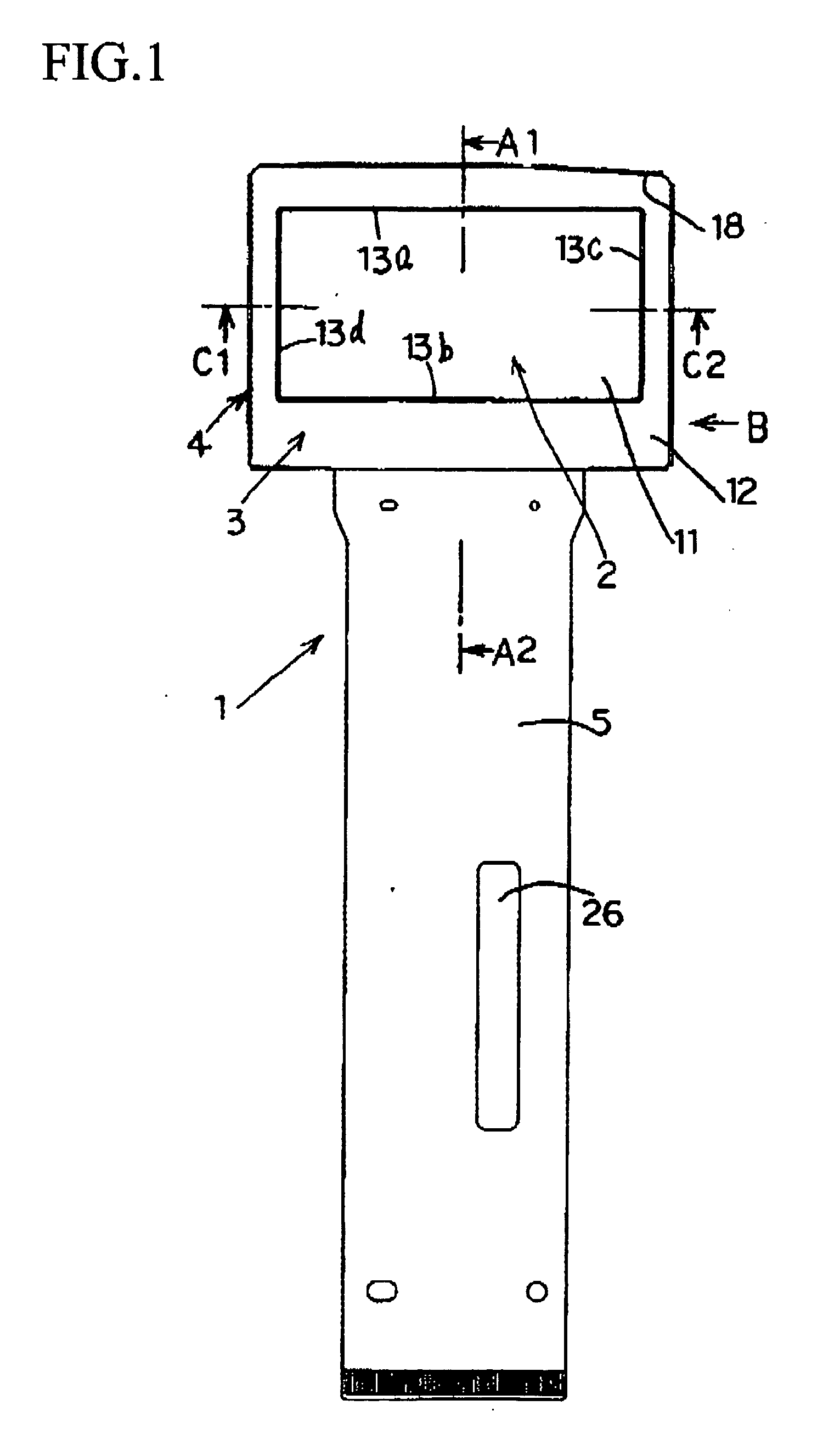
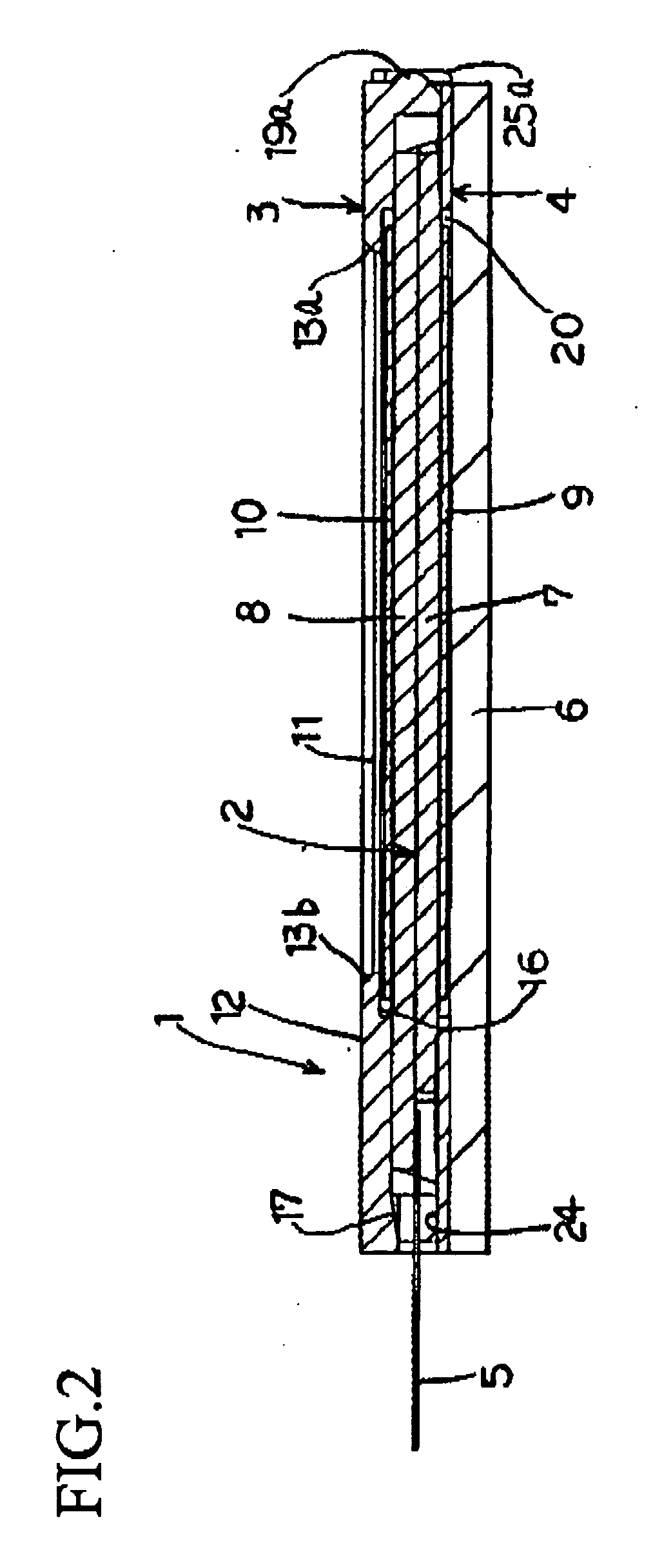
[0032] First, with reference to FIGS. 1 to 6, the structure of a liquid crystal display device 1 of this embodiment will be described.

[0033] As shown in FIGS. 1 to 6, the liquid crystal display device 1 is built with a liquid crystal cell 2, a frame body 3, a frame 4, an FPC (flexible printed circuit) board 5, a light source 6, and the like.

[0034] As shown in FIGS. 2 and 4, the liquid crystal cell 2 is built with a first insulating substrate 7, a second insulating substrate 8, a first polarizing pla...


PUM


Abstract

Provided is a liquid crystal display device that can be produced at low costs, can achieve miniaturization, and can offer clear virtual images. The liquid crystal display device is provided with: a frame body that is so disposed as to cover a top face of a liquid crystal cell, that has a first opening so formed as to face the top face of the liquid crystal cell, and that has a picture frame-shaped member formed around the first opening; a frame that is fixed to the frame body and that has a second opening so formed as to face a back face of the liquid crystal cell; and a light source that illuminates the liquid crystal cell via the second opening of the frame. Here, a top face of the picture frame-shaped member of the frame body is so designed that light is diffusely reflected therefrom.

Description

[0001] This application is based on Japanese Patent Application No. 2006-011305 filed on Jan. 19, 2006 and No. 2006-295533 filed on Oct. 31, 2006, the contents of which are hereby incorporated by reference. BACKGROUND OF THE INVENTION [0002] 1. Field of the Invention [0003] The present invention relates to a liquid crystal display device and a head-up display using it. [0004] 2. Description of Related Art [0005] There have conventionally been known head-up displays that display a virtual image indicating the speed or a virtual image for car navigation on the windshield of a vehicle. For example, such a head-up display is disclosed in JP-A-2005-082103. In the head-up display disclosed in JP-A-2005-082103, an image from the liquid crystal projector is projected onto the screen, and the projected image is then reflected on the windshield via the reflecting mirror. This allows the viewer to visually identify the virtual image projected via the liquid crystal projector as an image superi...

Claims


Application Information

Patent Timeline
Patent Type & Authority Applications(United States)
IPC IPC(8): G09G3/36
CPCG02B5/02G02B27/0101G02B2027/0118G02F2201/465G02F2001/13332G02F2201/38G02F1/133308G02F1/13332
Inventor NOGUCHI, SATOSHIKINUGAWA, TOMOKATSU
Owner EPSON IMAGING DEVICES CORP
Why Eureka
Try Eureka