Magnetic resonance system and method to detect and confirm analytes

a magnetic resonance and analyte technology, applied in the field of analyte detection, can solve the problems of large and expensive chemical analysis instruments, complex sample preparation, and inability to detect analyte, so as to reduce the false alarm rate, improve the detection effect, and enhance the quality of the result.

Inactive Publication Date: 2007-07-19
MENON INT
View PDF30 Cites 75 Cited by
  • Summary
  • Abstract
  • Description
  • Claims
  • Application Information

AI Technical Summary

Benefits of technology

The invention is a system that can detect substances in a sample by measuring magnetic resonance signals. The system can measure the signals at a single time or repeatedly over a period of time to improve detection. The system can also analyze the changes caused by the binding of the substance to nanoparticles to determine reaction rates or kinetics. This analysis can help confirm or clear the initial indication and improve the reliability and sensitivity of the detection process.

Problems solved by technology

The patent text discusses the need for improved detection technology for specific analytes in various fields such as laboratory instrumentation, industrial applications, and medical science. The technical problem addressed is the need for a compact and automated instrument to speed up measurements and understand the phenomena of agglomeration from a physics standpoint. The text also mentions the use of nanoparticles and magnetic fields to influence interactions between nanoparticles and molecules attached to nanoparticles, and the importance of using magnetic fields to concentrate reactants and accelerate selected interactions.

Method used


Image

  • Magnetic resonance system and method to detect and confirm analytes
  • Magnetic resonance system and method to detect and confirm analytes
  • Magnetic resonance system and method to detect and confirm analytes

Examples


Embodiment Construction

[0077]After reading this description it will become apparent to one skilled in the art how to implement the invention in various alternative embodiments and alternative applications. However, although various embodiments of the present invention will be described herein, it is understood that these embodiments are presented by way of example only, and not limitation. As such, this detailed description of various alternative embodiments should not be construed to limit the scope or breadth of the present invention as set forth in the appended claims.

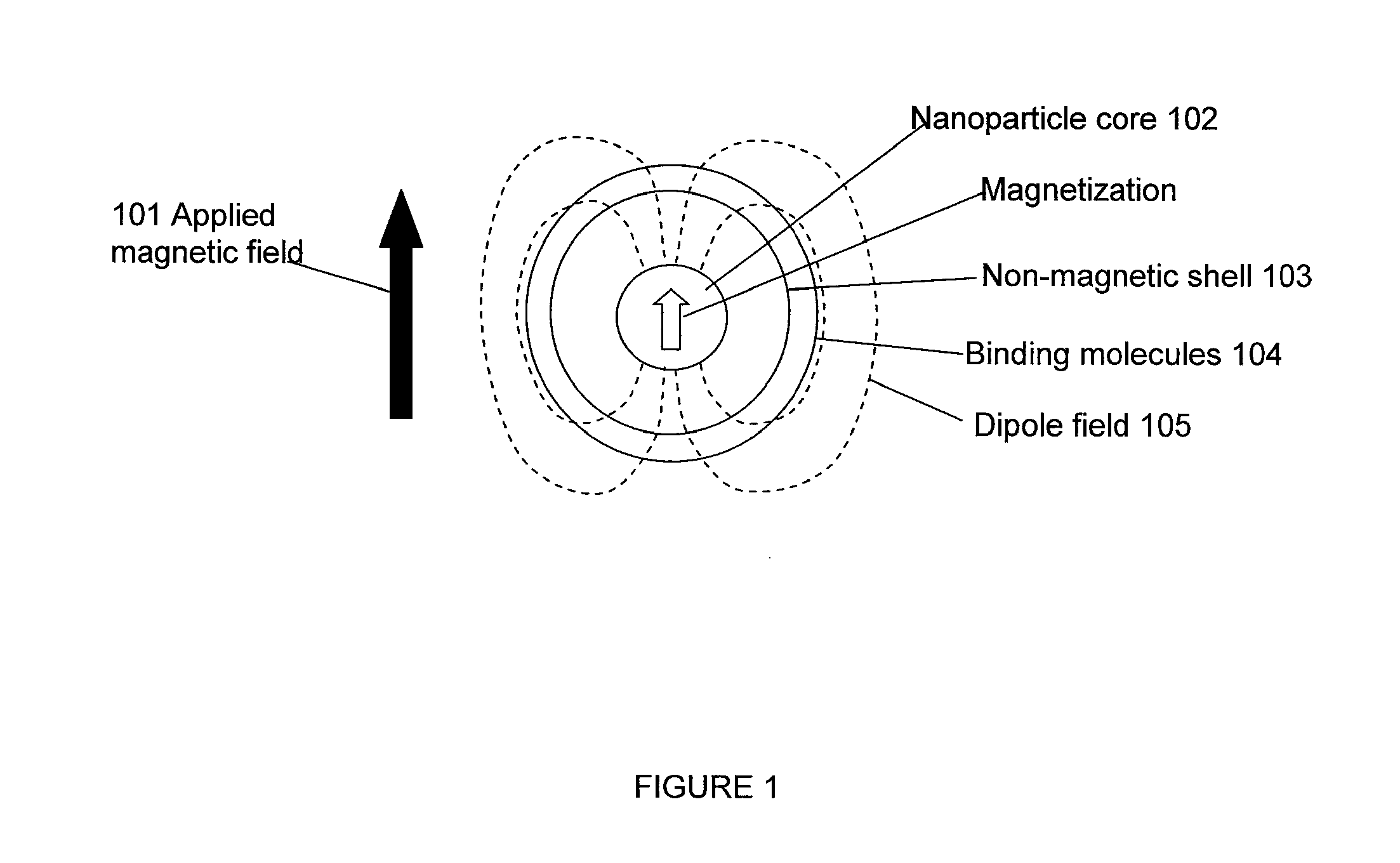
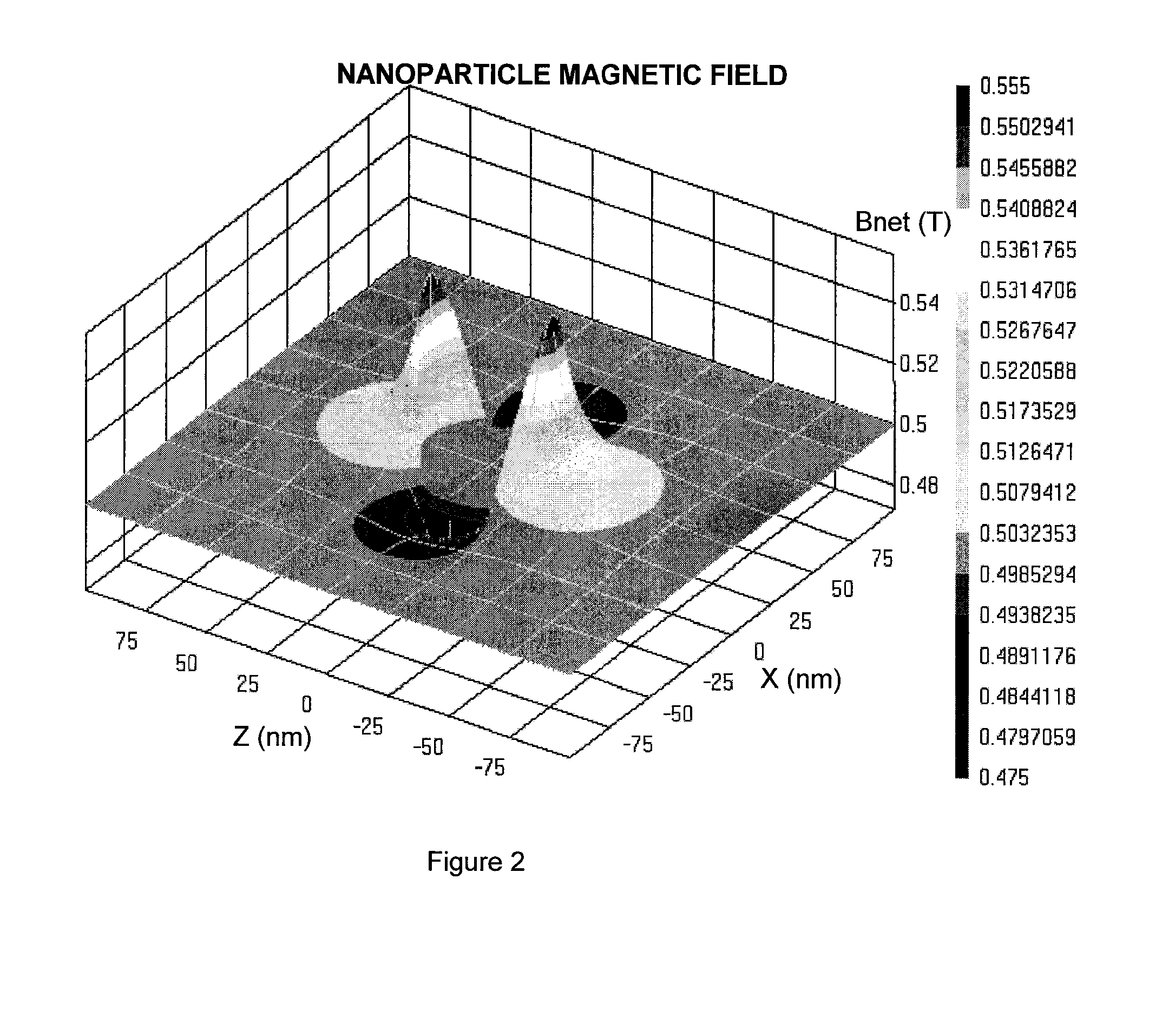
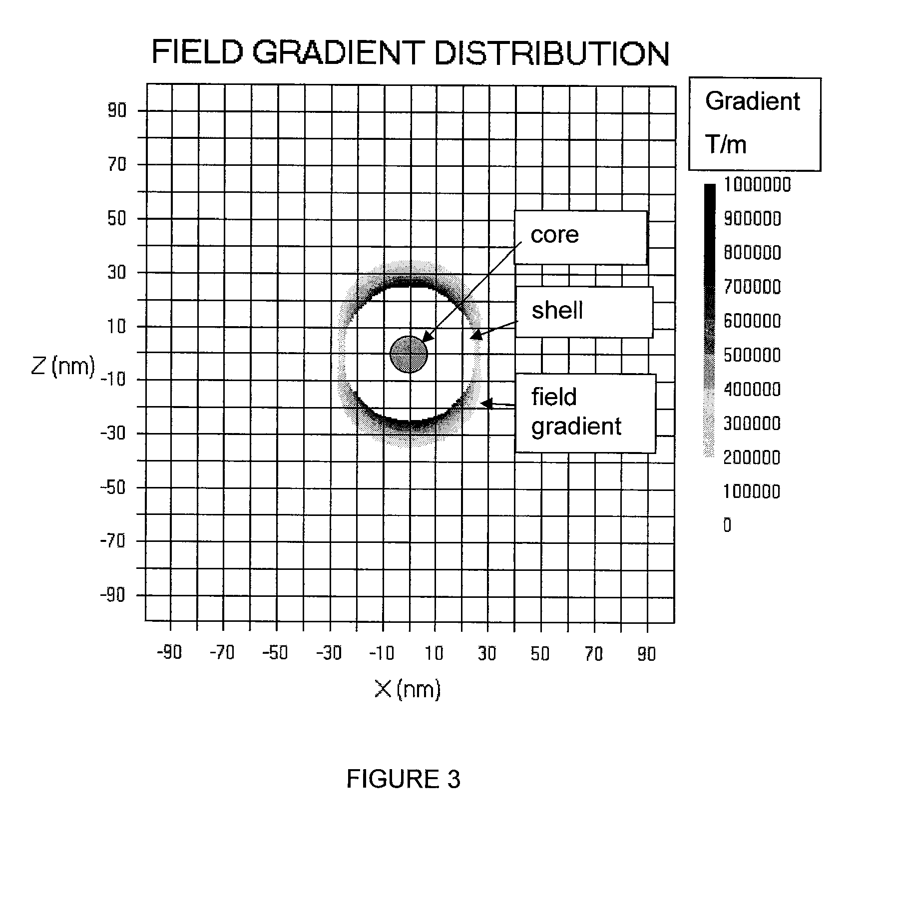
[0078]Magnetic Resonance

[0079]A brief summary of the technical elements used in certain embodiments is provided herein. The analyte or target molecule is contained in a medium, preferably a liquid such as water, which includes an atomic nucleus that has a non-zero spin, such as hydrogen. As is well known, (see for example, Pulse Methods in 1D & 2D Liquid-Phase NMR, Wallace S. Brey, Academic Press 1988), that the magnetic component of such...


PUM

PropertyMeasurementUnit
Forceaaaaaaaaaa
Concentrationaaaaaaaaaa
Magnetic fieldaaaaaaaaaa

Abstract

A system and method are provided to detect target analytes based on magnetic resonance measurements. Magnetic structures produce distinct magnetic field regions having a size comparable to the analyte. When the analyte is bound in those regions, magnetic resonance signals from the sample are changed, leading to detection of the analyte.

Description


Claims


Application Information

Patent Timeline
Owner MENON INT
Why Eureka
Try Eureka