Hierarchical Switching in Ultra-High Density Ultrasound Array

a high-density, multi-element technology, applied in the direction of sound producing devices, chiropractic devices, using reradiation, etc., can solve the problems of cumbersome and cost-prohibitive control of conventional switching mechanisms

Active Publication Date: 2007-07-19
INSIGHTEC
View PDF99 Cites 42 Cited by
  • Summary
  • Abstract
  • Description
  • Claims
  • Application Information

AI Technical Summary

Benefits of technology

[0007] In accordance with one aspect of the invention, systems and methods are provided for selectively connecting respective drive signals to respective transducer elements of an ultra-high density array of transducer elements in a focused ultrasound system. In one implementation, an ultrasonic transducer used for transmitting acoustic energy for thermal tissue treatment includes a relatively large number of transducer elements. By way of non-limiting example, the transducer may take the form of a flexible or semi-flexible strip that may be attached directly or indirectly to an exterior body surface for delivering targeted acoustic energy to tissue in an internal region of...

Problems solved by technology

While a switching mechanism may be used to connect an appropriate drive signal to the respective transducer elements, as the numb...

Method used


Image

  • Hierarchical Switching in Ultra-High Density Ultrasound Array
  • Hierarchical Switching in Ultra-High Density Ultrasound Array
  • Hierarchical Switching in Ultra-High Density Ultrasound Array

Examples


Embodiment Construction

[0017] In the following description, references to “one embodiment” or “an embodiment” mean that the feature being referred to is included in at least one embodiment of the invention. Further, separate references to “one embodiment” in this description do not necessarily refer to the same embodiment; however, neither are such embodiments mutually exclusive, unless so stated and except as will be readily apparent to those skilled in the art. In particular, the invention can include any variety of combinations and / or integrations of the embodiments described herein.

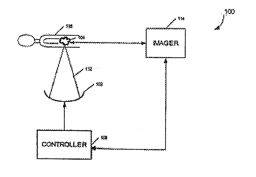
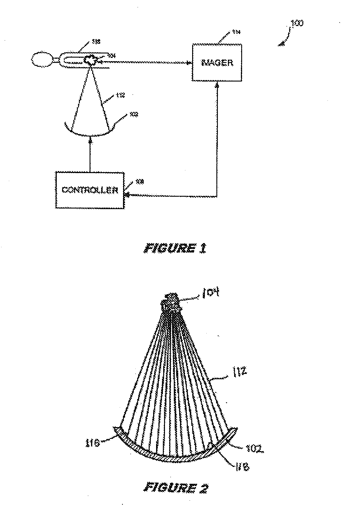
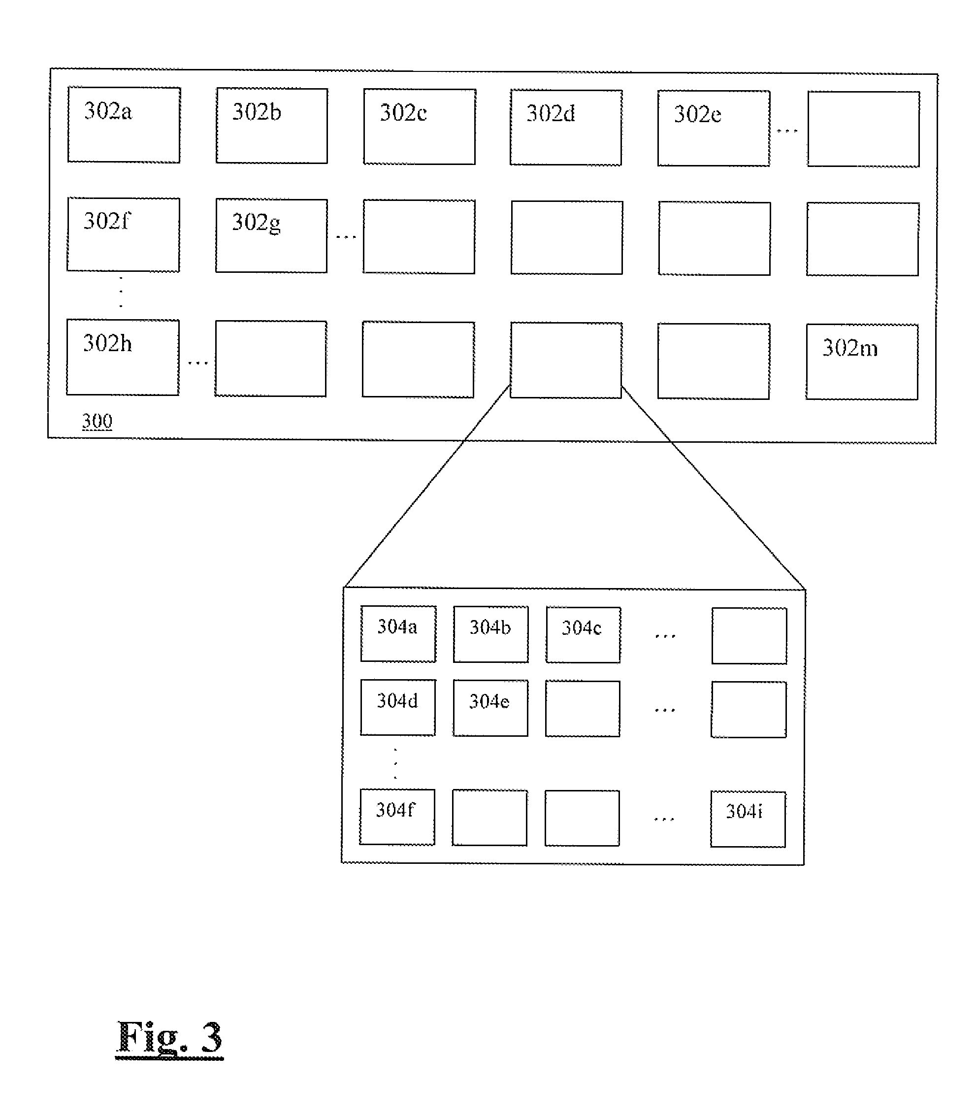
[0018] The invention relates to systems and methods for selectively coupling one of a number of discrete drive signals to selected transducer elements of a high density array. The transducer elements of the array may be divided into individual groupings, with each grouping of transducer elements selectively coupled to a respective drive signal. In this manner, each transducer element in a given grouping may operate with th...


PUM


Abstract

A focused ultrasound system comprises a transducer having a multiplicity of transducer elements, drive circuitry that generates and outputs a plurality of drive signals, each offset by a respective phase difference, and a controller for selectively coupling the drive signals to respective transducer elements, the controller including a plurality of first tier switching modules and second tier switching modules. Each first tier module receives as an input the plurality of drive signals and outputs one of the drive signals in response to a drive signal selection signal. Each second tier module is coupled to a respective grouping of transducer elements and selectively couples a respective selected drive signal output from a first tier switching module to one or more of the transducer elements in response to a transducer element selection signal.

Description

RELATED APPLICATION DATA [0001] The present application claims the benefit under 35 U.S.C. § 119 to U.S. provisional patent application Ser. No. 60 / 739,862, filed Nov. 23, 2005, which is hereby incorporated by reference.FIELD OF INVENTION [0002] This application relates generally to systems for delivering high intensity, therapeutic acoustic energy from a multi-element transducer, e.g., a high density, phased-array transducer, to a targeted tissue region in a patient. BACKGROUND [0003] It is well-known to use high intensity, focused acoustic wave energy, such as ultrasonic waves (i.e., acoustic waves having) a frequency greater than about 20 kilohertz.) to generate thermal ablation energy for treating internal body tissue, such as tumors. It is also well-known to employ an imaging system, such as a MRI system, in order to (guide the delivery of such high intensity ultrasound energy to the targeted tissue area, and to provide real-time feedback of the actual delivered thermal energy....

Claims


Application Information

Patent Timeline
IPC IPC(8): A61B8/00
CPCG01S15/8925G01S7/52019G10K11/346G01S15/8927A61B8/4494
Inventor VORTMAN, KOBIMEDAN, YOAVEZION, AVNER
Owner INSIGHTEC
Why Eureka
Try Eureka