Device and method for a trackable ultrasound

a technology of trackable ultrasound and ultrasound, applied in the field of trackable ultrasound devices, can solve the problem of small error in angular measurement by the sensor element to appear as a large error

Active Publication Date: 2007-07-19
UNITED STATES OF AMERICA +1
View PDF99 Cites 39 Cited by
  • Summary
  • Abstract
  • Description
  • Claims
  • Application Information

AI Technical Summary

Benefits of technology

[0006] In one embodiment, the invention provides a trackable ultrasound device such as, for example, a trackable laparoscopic ultrasound device, that may be used to produce merged images of preoperative scans and interoperative ultrasound images. In one embodiment, the trackable ultrasound device includes an ultrasonic transducer that generates an image of material existing along its scan plane. The trackable ultrasound device also includes a tracker, which is affixed to or near the ultrasonic transducer such that the tracker moves along with any movable parts of a scan head to which the ultrasonic transducer is attached. As affixed in this manner, the tracker enables the determination of the location, direction, and / or orientation of the scan plane even when the ultrasonic transducer moves relative to other parts of the ultrasound device.
[0007] In one embodiment, the ultrasonic transducer may include features that allow mating of the tracker to the scan head. Such features may include but are not limited to machined grooves, keyways, divots, alignment pins, spring-loaded balls to engage holes, alignment marks, or other features. These features may allow repeatable and accurate alignment and realignment of the tracker with the scan head.
[0011] In one embodiment, the invention provides for the prevention of relative movement between the tracker and the ultrasonic transducer by using alignment and engaging features (e.g., alignment elements) on the scan head, the tracker, and / or other parts of the device. This prevents the need for recalibration of the tracker to the ultrasonic transducer. For example, the alignment and engaging features enable the tracker to be removed and reliably replaced onto the scan head in the same position, while preserving an initial calibration (i.e., because the alignment features ensure that the relative positions of the tracker and the ultrasonic transducer remain the same).
[0012] In another embodiment, movement of the tracker relative to the ultrasonic transducer can be prevented by using the alignment and engaging features on the scan head, the tracker, and / or other portions of the ultrasound device to engage special jigs, thus eliminating the necessity of recalibration.
[0013] In one embodiment, if relative movement between the tracker and the ultrasonic transducer does occur after initial calibration (e.g., either by intentional remounting or for other reasons), the invention provides a method for adjusting the initial calibration, thus avoiding a time-consuming and / or difficult recalibration. This calibration adjustment method compensates for the relative movement between the tracker and the ultrasonic transducer using the tracker fiducial markings and the scan head fiducial markings.
[0018] A differential transformation matrix T is then calculated between Ttu (the primary transformation matrix) and T′tu (the secondary transformation matrix). The differential transformation matrix represents the difference between the first and second relative positions of the tracker and the ultrasonic transducer / scan head. Because the spatial relationships between the sensor elements and the scan plane are known relative to their respective fiducial markings (e.g., the tracker fiducial markings and the scan head fiducial markings) the differential transformation matrix provides an accurate representation of how to adjust the initial calibration.

Problems solved by technology

The “lever effect” causes a small error in angular measurement by the sensor element to appear as a large error in the position of the transducer.

Method used


Image

  • Device and method for a trackable ultrasound
  • Device and method for a trackable ultrasound
  • Device and method for a trackable ultrasound

Examples


Embodiment Construction

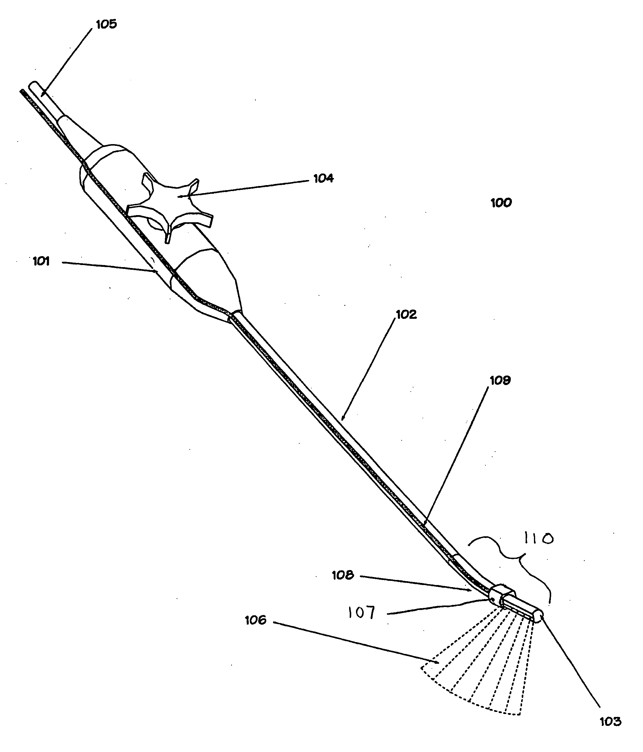
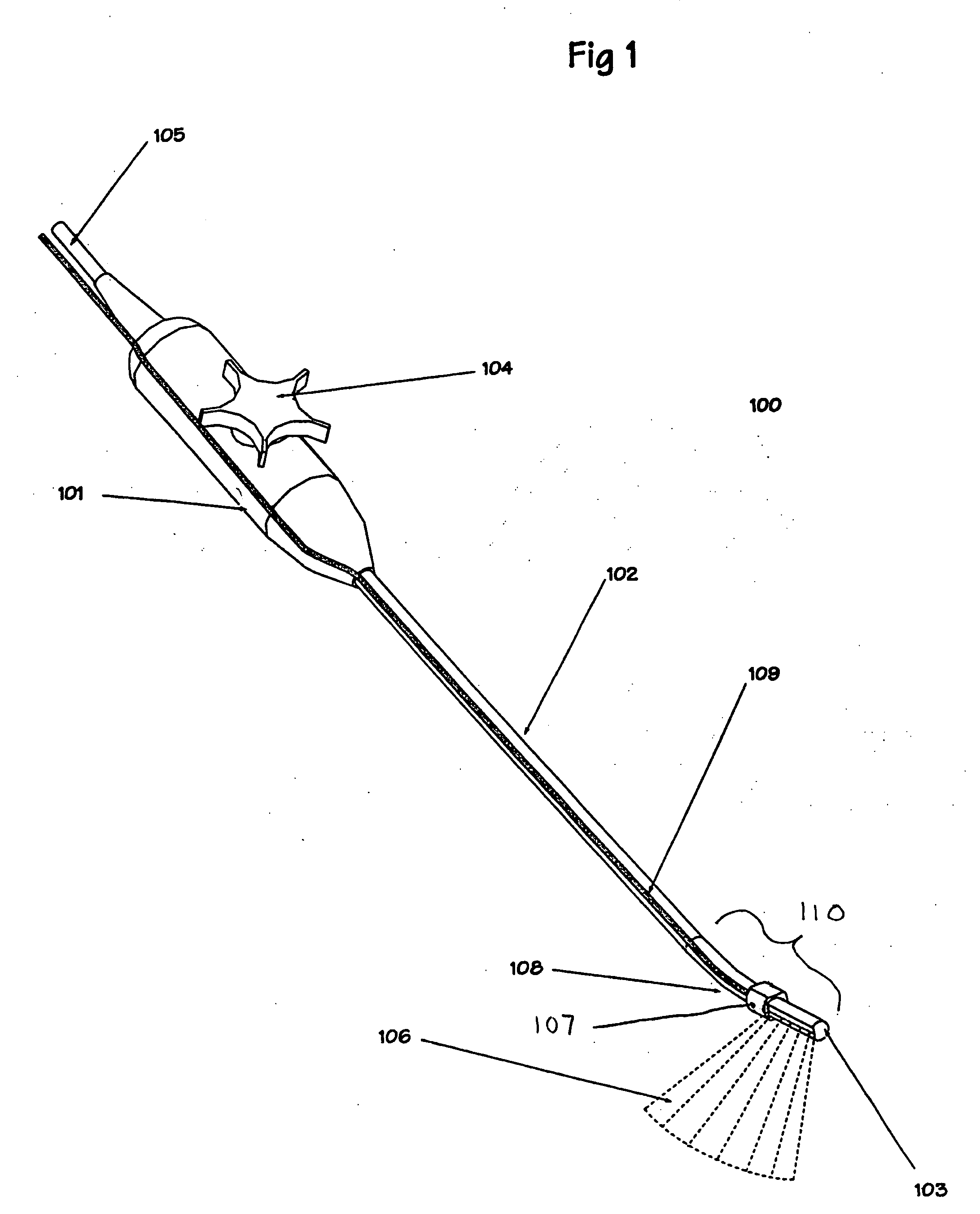
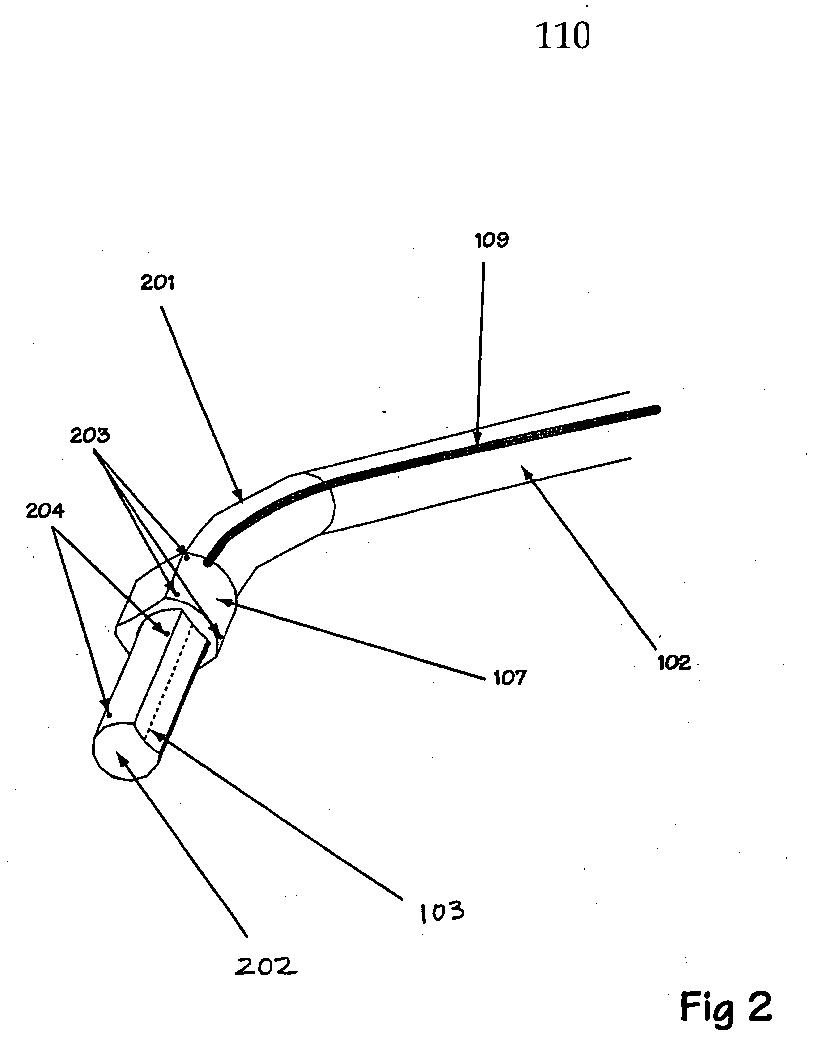
[0028] In one embodiment, the invention provides a device for tracking the ultrasonic transducer of an ultrasound device such as, for example, a trackable laparoscopic ultrasound device. FIG. 1 illustrates a trackable laparoscopic ultrasound device 100 according to an embodiment of the invention. In one embodiment, ultrasound device 100 includes a handle 101, an elongated shaft 102, a scan head 110, a control handle 104, a tracker 107, and / or other elements. Control handle 104 controls the pointing direction of a scan head 110, which includes an ultrasonic transducer 103.

[0029] Signals are sent to and from ultrasonic transducer 103 via cable 105, which may be routed through the interior of handle 101 and elongated shaft 102. In other embodiments, cable 105 may be routed or located elsewhere.

[0030] Trackable laparoscopic ultrasound device 100 is designed to generate an image of material existing along a scan plane 106, which extends from ultrasonic transducer 103. In one embodiment...


PUM


Abstract

The invention provides a method for adjusting the calibration of a tracked ultrasound device using the measured difference between two sets of fiducial markings in two relative positions of a tracker and an scan head of the device. The invention also provides a trackable ultrasound device that enables repeatable attachment of a tracker to a scan head, thus preserving an initial calibration between the tracker and the scan head. Furthermore, the invention provides a calibration jig that can be used to repeatably attach a tracker to an ultrasound scan head or to measure the difference between two relative positions of a tracker and a scan head.

Description

REFERENCE TO RELATED APPLICATIONS [0001] This application claims priority to U.S. Provisional Patent Application No. 60 / 692,271, filed Jun. 21, 2005, which is hereby incorporated by reference herein in its entirety.STATEMENT REGARDING FEDERALLY SPONSORED RESEARCH AND DEVELOPMENT [0002] This invention may be supported by the Department of Health and Human Services. The Government of the United States of America may have certain rights in the invention disclosed and claimed below.FIELD OF THE INVENTION [0003] The invention provides a device and method for tracking an ultrasound. BACKGROUND [0004] Ultrasound devices typically include an ultrasonic transducer with scan / receive heads, a processing unit, and a display device. Ultrasonic transducers may be adapted for special applications such as, for example, transcutaneous applications, laparoscopic applications, transrectal applications, endo-cavity probes, vaginal probes, 2D and 3D phased array probes, and / or other probes or applicatio...

Claims


Application Information

Patent Timeline
Patent Type & Authority Applications(United States)
IPC IPC(8): A61B8/00
CPCA61B8/00A61B8/12A61B8/445A61B8/58A61B8/4245
Inventor GLOSSOP, NEIL DAVIDWOOD, BRADFORD JOHNS
Owner UNITED STATES OF AMERICA
Why Eureka
Try Eureka