Multi-element probe array

a probe array and multi-element technology, applied in the field of multi-element probe arrays, can solve the problems of difficult and time-consuming process, medical applications raise particularly challenging demands on probes, and subject injury

Inactive Publication Date: 2007-07-19
STERLING INVESTMENTS LC
View PDF39 Cites 39 Cited by
  • Summary
  • Abstract
  • Description
  • Claims
  • Application Information

AI Technical Summary

Problems solved by technology

Medical applications raise particularly challenging demands on a probe to be used for sensing or stimulation.
This process is difficult and time consuming, and mistakes can lead to injury to the subject.
Single probes are also difficult to fix in position without causing injury.
The resulting arrays suffer from several drawbacks.
The individual probe elements are brittle and relatively large compared to the size of nerve endings.
Additionally, known probe arrays have relatively widely spaced probe tips, providing lower spatial resolution than desired.

Method used


Image

  • Multi-element probe array
  • Multi-element probe array
  • Multi-element probe array

Examples


Embodiment Construction

[0015] The following detailed description of exemplary embodiments of the invention makes reference to the accompanying drawings, which form a part hereof and in which are shown, by way of illustration, exemplary embodiments in which the invention may be practiced. While these exemplary embodiments are described in sufficient detail to enable those skilled in the art to practice the invention, it should be understood that other embodiments may be realized and that various changes to the invention may be made without departing from the spirit and scope of the present invention. Thus, the following more detailed description of the embodiments of the present invention is not intended to limit the scope of the invention, as claimed, but is presented for purposes of illustration only and not limitation to describe the features and characteristics of the present invention, to set forth the best mode of operation of the invention, and to sufficiently enable one skilled in the art to practi...


PUM

PropertyMeasurementUnit
diameteraaaaaaaaaa
diameteraaaaaaaaaa
diameteraaaaaaaaaa

Abstract

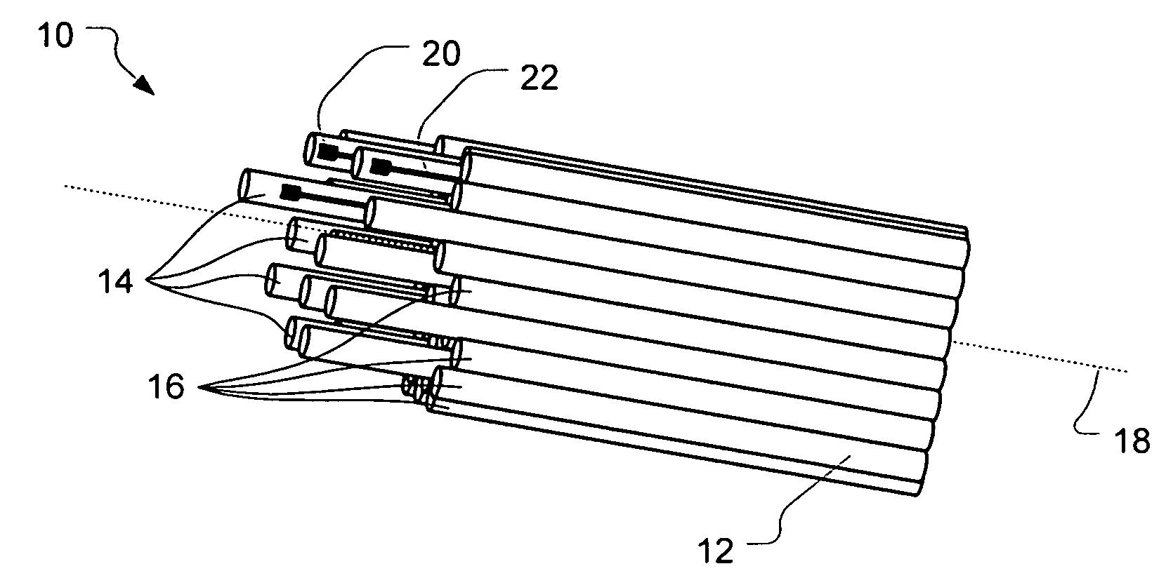
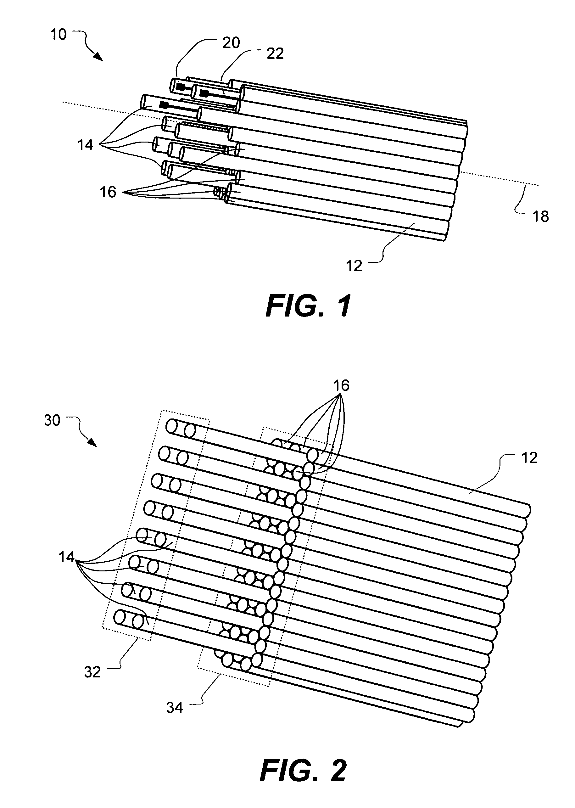
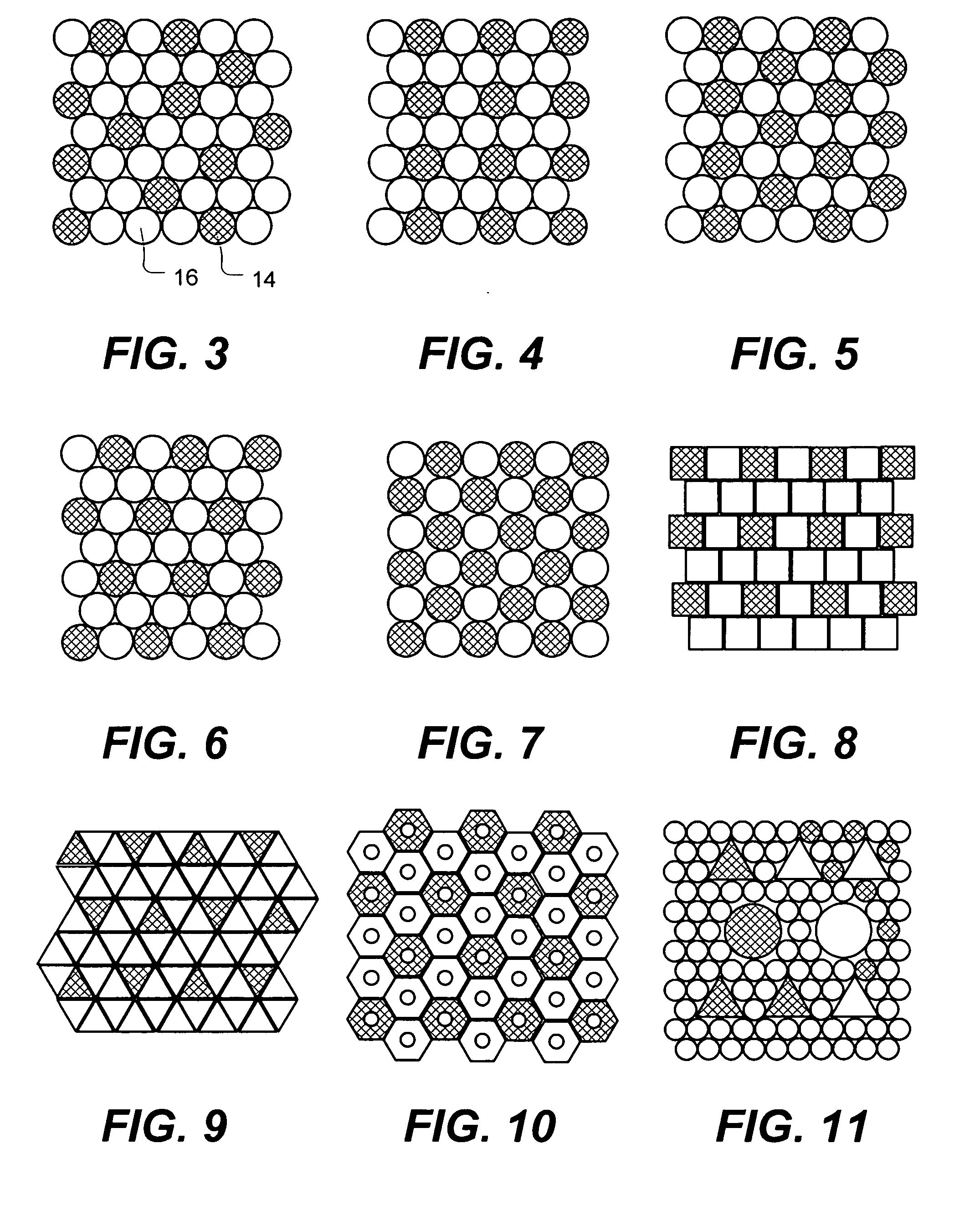
A multi-element probe array suitable for sensing or stimulating is disclosed. In one embodiment, the multi-element probe array includes a plurality of microfibers extending longitudinally and oriented substantially parallel to form a bundle. Probe elements are defined by a first subset of the microfibers displaced in a forward direction alone the longitudinal axis relative to spacer elements defined by a second subset of the microfibers. Interface elements and communication elements are disposed on the probe elements.

Description

[0001] This application claims the benefit of U.S. Provisional Patent Application Ser. No. 60 / 749,777, filed Dec. 12, 2005, entitled “Ultra-High Density Electrical Connector” and U.S. Provisional Patent Application Ser. No. 60 / 749,873, filed Dec. 12, 2005 entitled “Multi-Element Probe Array,” each of which is incorporated by reference.BACKGROUND OF THE INVENTION AND RELATED ART [0002] Various types of probes have found applications in chemical sensing, electronics testing, and medicine. Medical applications raise particularly challenging demands on a probe to be used for sensing or stimulation. For example, probes intended for use in interfacing directly to human tissue present several conflicting requirements. On one hand, it is desirable that a probe be quite rigid and strong so that it can be pushed through human tissue without breaking or deforming. On the other hand, it is desirable that a probe be very small, to minimize tissue damage, and flexible, so that is can move with th...

Claims


Application Information

Patent Timeline
Patent Type & Authority Applications(United States)
IPC IPC(8): A61B8/14
CPCA61B5/04001A61B5/6868A61B5/6877Y10T29/49117A61N1/0551H01R11/18H01R2201/12A61N1/0529A61B5/24
Inventor JACOBSEN, STEPHEN C.MARCEAU, DAVID P.ZURN, SHAYNE M.
Owner STERLING INVESTMENTS LC
Why Eureka
Try Eureka