Stent Delivery System

a technology of stent and inner member, which is applied in the field of medical devices, can solve the problems of limited control during deployment, difficult to maintain the position of the inner member, and the tendency of the stent to escape from the inner member, and achieve the effect of high degree of control

Active Publication Date: 2007-07-19
CR BARD INC
View PDF105 Cites 167 Cited by
  • Summary
  • Abstract
  • Description
  • Claims
  • Application Information

AI Technical Summary

Benefits of technology

[0013]It is therefore an object of the invention to provide a stent delivery system that permits a high degree of control during the deployment of the stent.
[0014]It is another object of the invention to provide a stent delivery system that more easily retracts an outer jacket at different speeds.
[0016]It is yet another object of the invention to provide a stent delivery system with independent outer jacket retraction controls that allow switching from one control to another without a lag in the jacket retraction.
[0018]Preferably, the thumbwheel and the thumb lever retract the jacket by way of a cord within the handle of the delivery system that engages a proximal portion of the jacket. The thumbwheel rotates a spool which winds up the cord and therefore causes the jacket to retract. The thumb lever effectively increases the path of the cord within the handle by moving against a region of the cord, also causing the jacket to retract. The pull ring is preferably connected to the proximal end of the jacket, allowing the user to directly pull the jacket in a proximal direction.
[0019]Each of the jacket controls can be configured to provide the user with different retraction ratios (e.g. for every 1 cm of movement of the thumb lever the jacket retracts 2 cm). In this respect, the user can use different retraction controls at different stages in the delivery procedure. For example, the user may wish to initially retract the jacket slowly to “flower” the stent, with the thumbwheel. However, once the stent has been flowered, the user may wish to more quickly retract the jacket with the lower ratio of the thumb lever or pull ring. In this respect, the stent delivery system allows the user to more easily retract the jacket at different speeds during the delivery procedure.

Problems solved by technology

However, it is very difficult to maintain the position of the inner member while moving the outer member to deploy the stent.
As such, the degree of control during deployment is limited.
Under such limited control there is a tendency for the stent to escape from the inner member before the jacket is fully retracted and jump from the desired deployment site.
This may result in deployment of the stent at a location other than the desired implant site.
First, the handle is not particularly well suited to short stents as there is little fine control.
Second, the handle is not well-suited to long stents, e.g., above 90 mm in length, as the linear control requires the operator to change his or her grip during deployment in order to generate the large relative motion of the tubular components.
The result can be an unintentionally rapid and possibly uneven deployment of the stent.
Fourth, without reference to a fluoroscope monitoring the stent, there is no manner to determine from the proximal end of the instrument the progress of stent deployment.
Fifth, the construction of the inner tubular member and outer jacket may cause the inner member and jacket to be crushed during use.
Furthermore, the inner tubular member is subject to compressive force during deployment and may deform while moving the stent from the desired deployment location.
In these designs, the retraction speed of the jacket member is limited by both the user's ability to actuate the thumbwheel (i.e. the speed the user can move their thumb) and the retraction ratio of the thumbwheel (i.e. the ratio of thumbwheel movement / rotation to jacket retraction).
This “speed limit” can be especially difficult for a user when deploying longer stents such as those between 100 and 200 mm in length, since it greatly increases the stent deployment time.
Further, the thumbwheel can have only one retraction ratio, which increases the difficulty of retracting the jacket at substantially different speeds.

Method used


Image

  • Stent Delivery System
  • Stent Delivery System
  • Stent Delivery System

Examples


Embodiment Construction

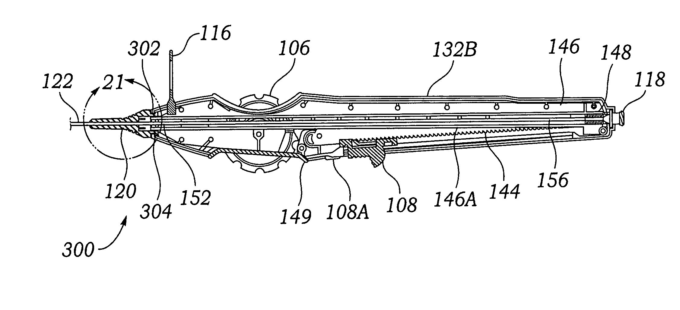
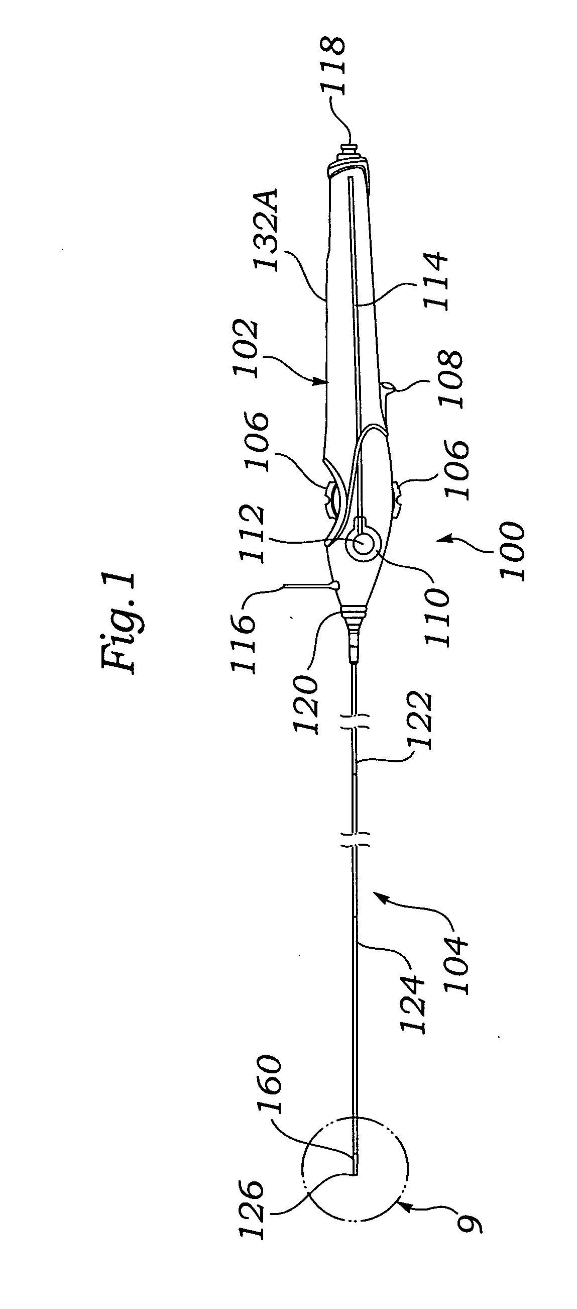
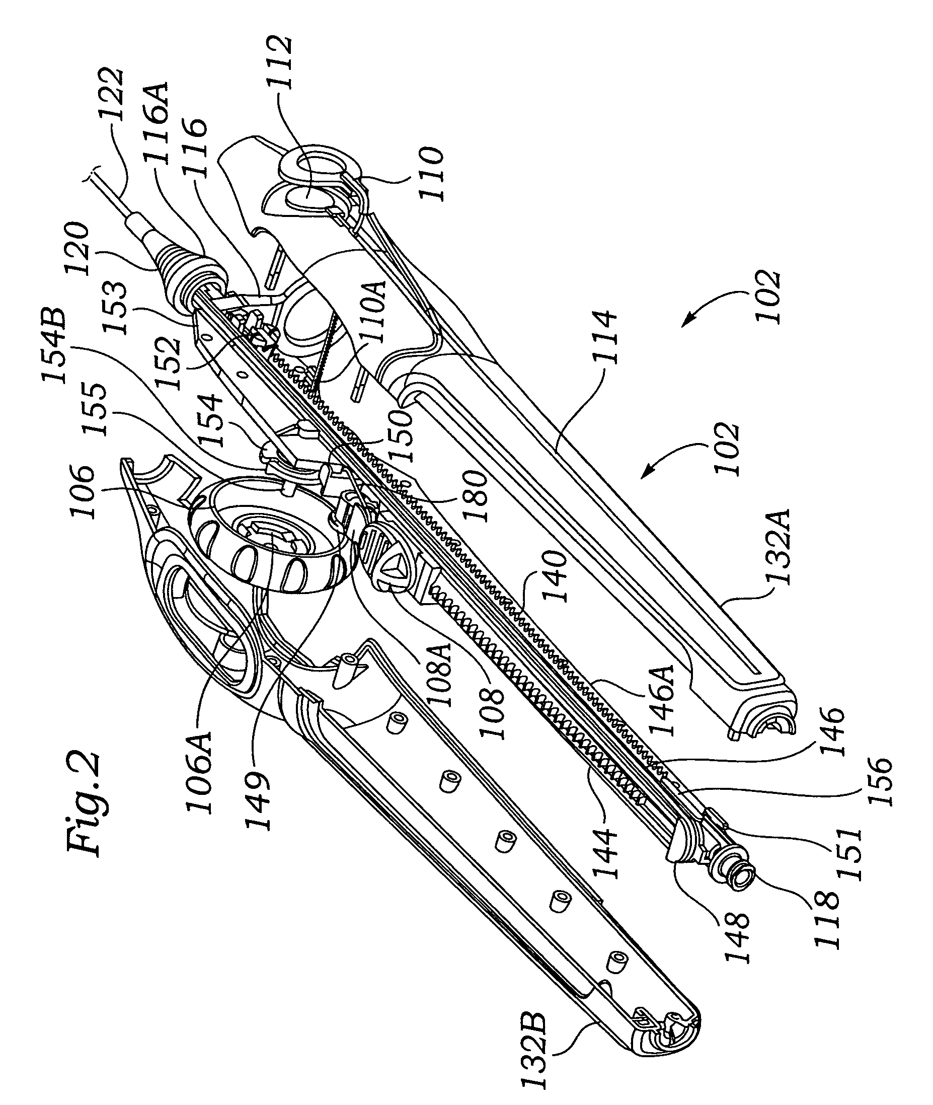
[0043]FIGS. 1-14 illustrate a preferred embodiment of a stent delivery system 100 according to the present invention which includes multiple mechanisms for retracting an outer tubular member 124 (also referred to as a jacket or sheath in this specification) to deliver a prosthesis, such as a stent 160 in the current example. As seen in FIG. 1, the stent delivery system 100 includes a thumbwheel 106, a deployment lever 108, and a rapid deployment ring 110, each providing a different approach to retracting the outer tubular member 124 and therefore deploying the stent 160 or other prosthesis.

[0044]Each of the three deployment controls provides different actuation methods that facilitate deployment of the stent 160 at different speeds. For example, the thumbwheel 106 allows the user to slowly deploy the stent 160 with slow and precise thumb movement, while the rapid deployment ring 110 provides the user leverage to deploy the stent 160 in a more rapid fashion.

[0045]Additionally, some o...


PUM


Abstract

One preferred embodiment includes a stent delivery system including a retractable sheath and an outer stability sheath. The stability sheath freely rotates relative to the retractable sheath, relieving compression forces caused by twisting of stability sheath in when in a tortuous conformation.

Description

RELATED APPLICATION[0001]The present application claims priority under 35 U.S.C. §119(e) to U.S. provisional application 60 / 759,136, filed Jan. 13, 2006 and provisional application 60 / 789,734, filed Apr. 5, 2006.FIELD OF INVENTION[0002]This invention relates broadly to medical devices. More particularly, this invention relates to an instrument for delivering a self-expanding stent into a mammalian body and controllably releasing the stent.BACKGROUND OF THE INVENTION[0003]Transluminal prostheses are widely used in the medical arts for implantation in blood vessels, biliary ducts, or other similar organs of the living body. These prostheses are commonly known as stents and are used to maintain, open, or dilate tubular anatomical structures.[0004]The underlying structure of the stent can be virtually any stent design. There are typically two types of stents: self-expanding stents and balloon expandable stents. Stents are typically formed from malleable metals, such as 300 series stainl...

Claims


Application Information

Patent Timeline
Patent Type & Authority Applications(United States)
IPC IPC(8): A61F2/84
CPCA61F2/95A61F2002/9517A61F2/966A61F2/9517
Inventor JIMENEZ, TEODORO S.FULKERSON, JOHNMAZZEI, RAFFAELE
Owner CR BARD INC
Why Eureka
Try Eureka