Systems and methods for laser-assisted plasma processing

a laser-assisted plasma and processing system technology, applied in the field of selective removal, can solve the problems of supplying enough heat to evenly heat an entire workpiece, affecting the quality of laser-assisted plasma, and presenting a number of formidable challenges to fabricators, so as to achieve a smaller and more precise footprint, improve process efficiency, and high controllability

Inactive Publication Date: 2007-11-20
IMREAL ENTERPRISES
View PDF13 Cites 30 Cited by
  • Summary
  • Abstract
  • Description
  • Claims
  • Application Information

AI Technical Summary

Benefits of technology

[0011]Systems and methods in accordance with embodiments of the present invention can overcome deficiencies and obstacles in existing plasma etching processes by selectively heating portions of a workpiece, and etching those heated portions using a reactive atom process. Such an etching process can be highly-controllable, precise, atmospheric, and non-contact, with a footprint that is smaller and more precise than in existing systems. Further, such an approach can avoid many problems in existing systems wherein the entire workpiece is heated. Such systems and methods can also provide improved processes for rapidly etching hard-to-machine materials using a flame torch or plasma torch in combination with a heat source such as a laser or flame torch.

Problems solved by technology

Modern materials present a number of formidable challenges to the fabricators of a wide range of optical, semiconductor, and electronic components, many of which require precision shaping, smoothing, and polishing.
Some aspects of this process are problematic.
When the workpiece is very large, supplying enough heat to evenly heat an entire workpiece can be problematic, especially when temperature A is large.
Another drawback is the amount of time necessary to heat a workpiece, as heating a workpiece too quickly can induce thermal stresses which are undesirable in high precision components.

Method used


Image

  • Systems and methods for laser-assisted plasma processing
  • Systems and methods for laser-assisted plasma processing
  • Systems and methods for laser-assisted plasma processing

Examples


Embodiment Construction

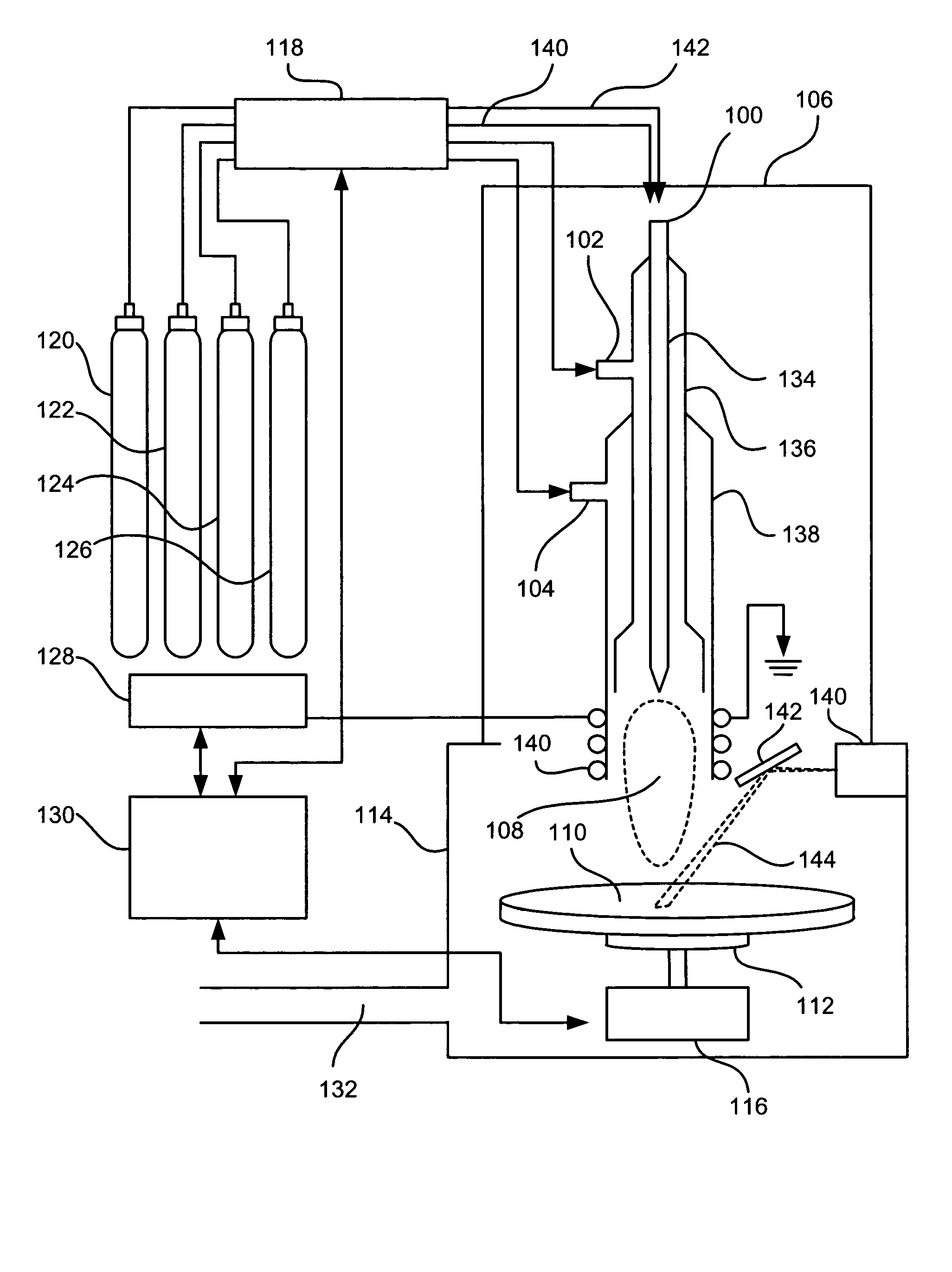
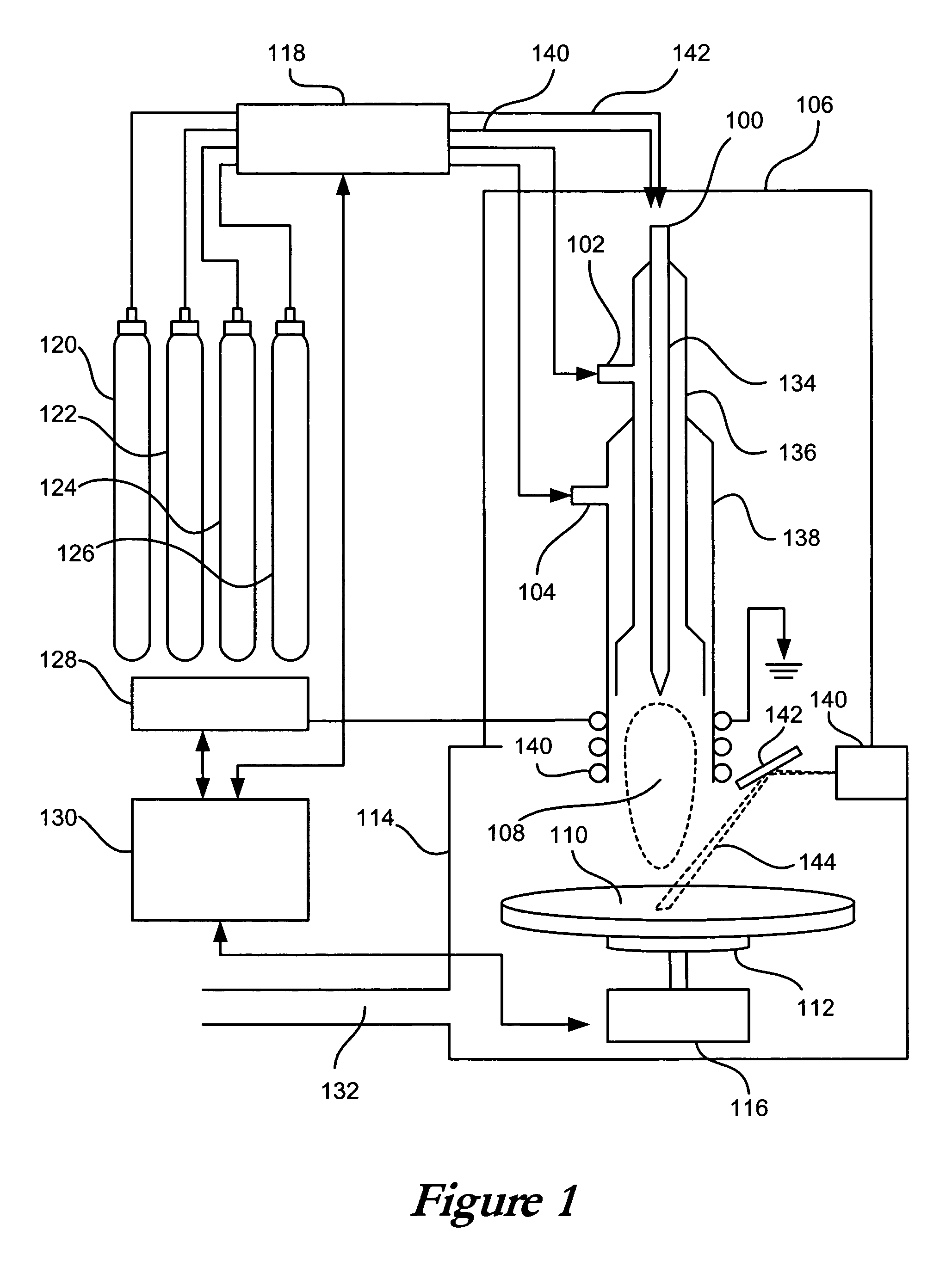
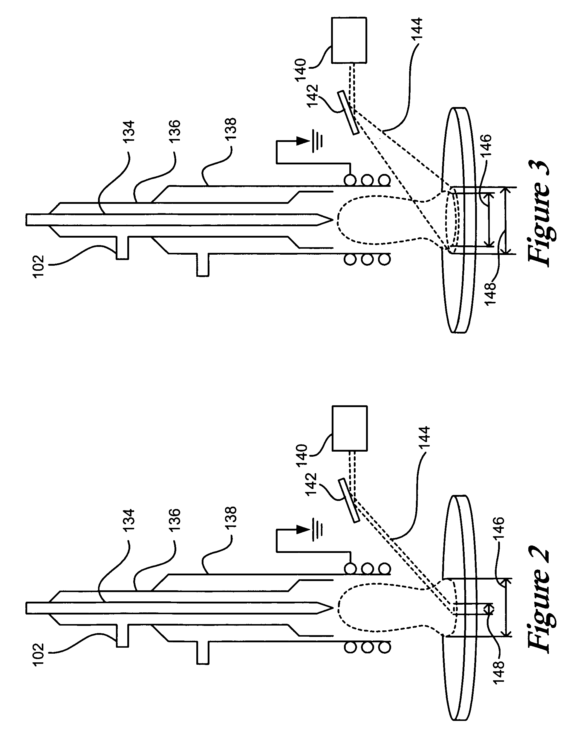
[0020]Systems and methods in accordance with embodiments of the present invention can circumvent problems associated with heating an entire workpiece to a specified temperature such that the workpiece can be etched using a sub-aperture tool. A heat source having a footprint that is smaller than the size of the workpiece, such as a laser, plasma, or flame can be used to heat a specific portion of the workpiece surface to a desired temperature. Such a process can provide many advantages, and can substantially improve the performance of a sub-aperture plasma-etching process. Applications for such a process can include, for example, any application where a high-aspect ratio hole needs to be created with a diameter that is less than that of a plasma footprint. Such applications can include, for example, applications requiring the drilling of human teeth, which cannot handle the thermal stress induced by lasers alone, and the generation of micro-holes to mark diamonds. The diameters of th...


PUM

PropertyMeasurementUnit
diametersaaaaaaaaaa
diametersaaaaaaaaaa
sizeaaaaaaaaaa

Abstract

A controllable heat source, such as a laser or flame torch, can be used to pre-heat a portion of the surface of a workpiece, such as a glass optic or semiconductor wafer. Reactive atom plasma (RAP) processing can be used to modify the pre-heated surface portion, as the pre-heated material will more readily chemically combine with the atomic radicals of the precursor in the plasma. A RAP torch, such as an ICP plasma torch, MIP plasma torch, or flame torch, can be used to shape, polish, etch, planarize, deposit, chemically modify and / or redistribute material on the surface of the workpiece. The material modified by the torch can substantially correspond to the pattern or portion of the surface that was pre-heated by the heat source. This description is not intended to be a complete description of, or limit the scope of, the invention. Other features, aspects, and objects of the invention can be obtained from a review of the specification, the figures, and the claims.

Description

CLAIM OF PRIORITY[0001]This application claims priority to U.S. provisional patent application No. 60 / 495,194, entitled “Systems and Methods for Laser-Assisted Plasma Processing,” by Jude Kelley, et al., filed Aug. 14, 2003.CROSS-REFERENCED CASES[0002]The following applications are cross-referenced and incorporated herein by reference:[0003]U.S. patent application Ser. No. 10 / 008,236 entitled “Apparatus and Method for Reactive Atom Processing for Material Deposition,” by Jeffrey W. Carr, filed Nov. 7, 2001.[0004]U.S. patent application Ser. No. 10 / 383,478 entitled “Apparatus and Method Using a Microwave Source for Reactive Atom Plasma,” by Jeffrey W. Carr, filed Mar. 7, 2003.[0005]U.S. patent application Ser. No. 10 / 384,506 entitled “Apparatus and Method for Non-Contact Cleaning of a Surface,” by Jeffrey W. Carr, filed Mar. 7, 2003.FIELD OF THE INVENTION[0006]The field of the invention relates to the selective removal of material from a surface.BACKGROUND[0007]Modern materials prese...

Claims


Application Information

Patent Timeline
Patent Type & Authority Patents(United States)
IPC IPC(8): B23K9/00B23K9/02B08B7/00C03C15/00C03C23/00C04B41/53C04B41/91G02B6/136H05H1/30
CPCB08B7/0035C03C15/00H05H1/30G02B6/136C04B41/91C04B41/5346C04B41/009C03C23/006C03C23/0075C04B41/0036C04B35/14C04B35/565
Inventor KELLEY, JUDECARR, JEFFREY W.FISKE, PETER S.
Owner IMREAL ENTERPRISES
Why Eureka
Try Eureka