
Method and instruments for intervertebral disc augmentation through a pedicular approach

a pedicular approach and intervertebral disc technology, applied in the field of pedicular approach for intervertebral disc augmentation, can solve the problems of inability to repair, inability to suture the hole, and inability to repair, so as to reduce the risk of extravasation or leakage, and repair the damage to the breached vertebral endplate.

Inactive Publication Date: 2007-07-19
DEPUY SPINE INC (US)
View PDF15 Cites 27 Cited by
  • Summary
  • Abstract
  • Description
  • Claims
  • Application Information

AI Technical Summary

Benefits of technology

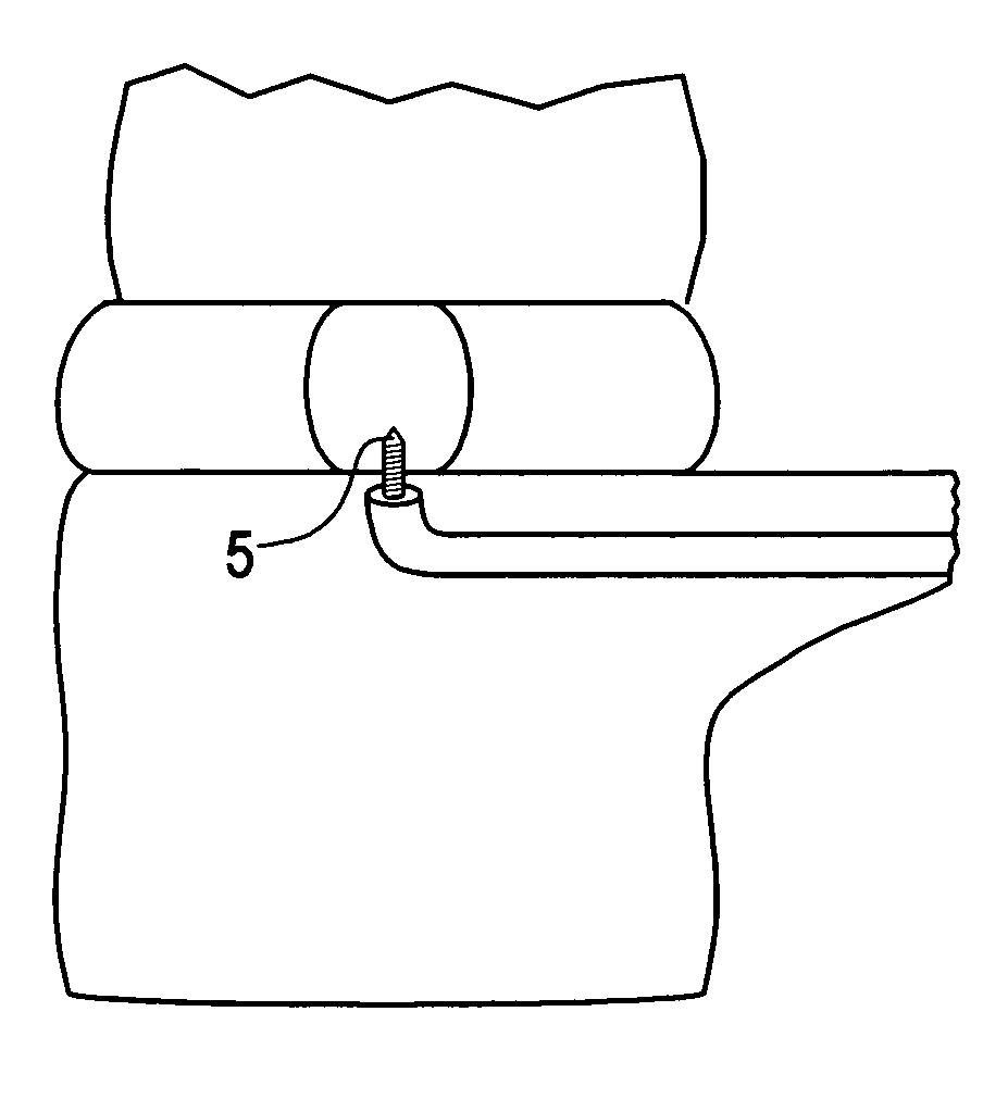
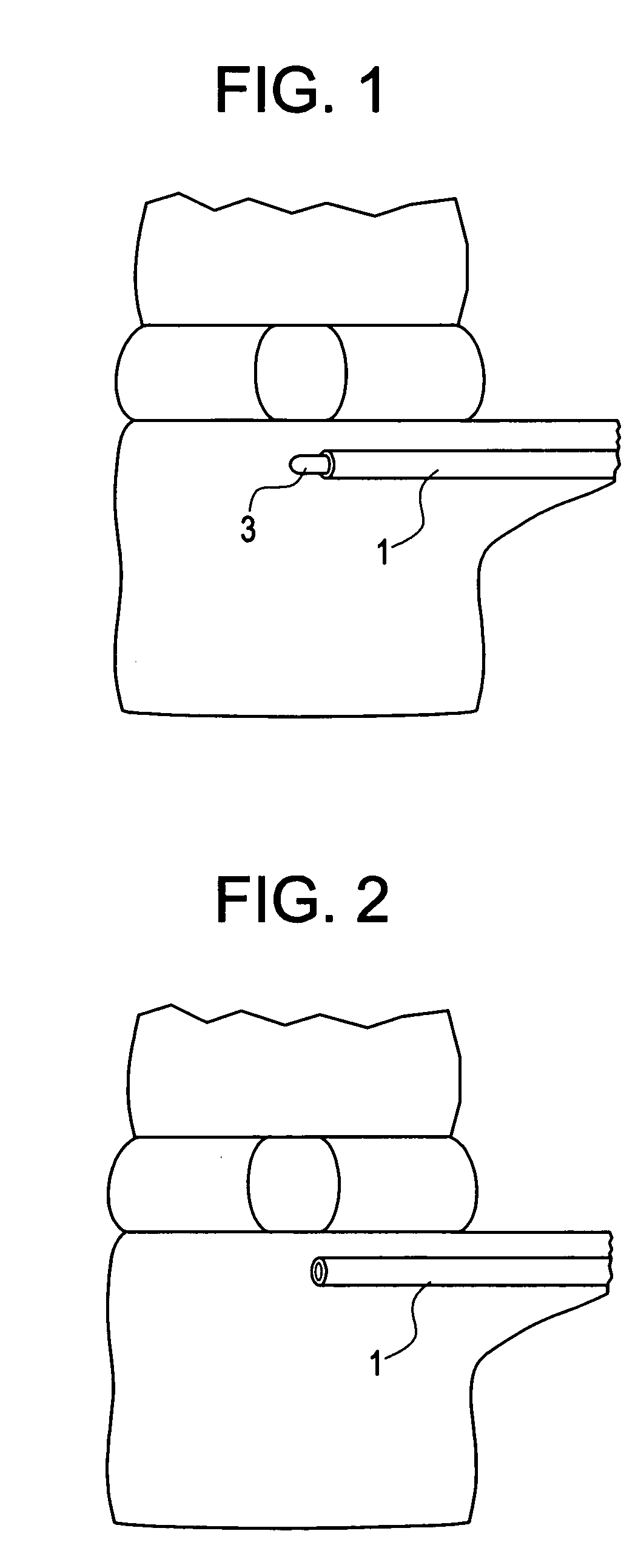
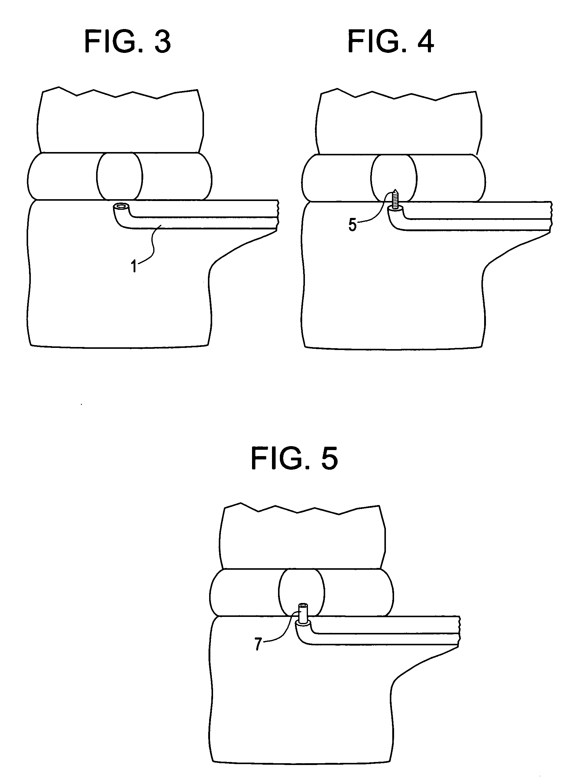
[0008] The present invention provides a method of filling the disc with flowable nucleus pulposus augmentation material without damaging the annulus fibrosus. In particular, the present invention creates a throughbore through an adjacent vertebral body that accesses the disc through the vertebral endplate. This throughbore is then used as a conduit to fill the disc with a flowable augmentation material. After the disc is filled, the damage to the breached vertebral endplate is repaired. However, because the endplate may be repaired with well known techniques for repairing bone, there is much less risk of extravasation or leakage when compared to that associated with the repair of a damaged annulus fibrosus.

Problems solved by technology

One problem with this approach is that access to the nucleus pulposus requires breach of the annulus fibrosus, an avascular cartilaginous structural that heals slowly, if at all.
However, such repair is often imperfect and there remains a risk of expulsion of the nucleus augmentation materials through the sutured hole.
However, this drastically limits the types of materials that can be used for disc augmentation.
McAfee does not teach flowing a fluid nucleus pulposus replacement material through the pedicle channels to the disc space.
Cragg does not disclose accessing the nucleus via the pedicle, nor repairing the endplate after access has been made.

Method used


Image

  • Method and instruments for intervertebral disc augmentation through a pedicular approach
  • Method and instruments for intervertebral disc augmentation through a pedicular approach
  • Method and instruments for intervertebral disc augmentation through a pedicular approach

Examples


example i

[0090] A patient with discogenic back pain with a black disc at L 4-5 is to be treated with disc augmentation along with a motion preserving posterior instrumentation system. The patient is prepped for a posterior approach. The pedicles are tapped at L4 and L5 to prepare for screw placement. A Nitonol tube with a harp tipped obdurator is inserted through one of the pedicle screw holes at L5 and advanced into the vertebral body. The nitinol tube system curves upwards so as to contact the endplate. The obdurator is then removed and replaced with a flexible drill to create a hole through the endplate into the disc. The drill is then removed and the disc contents are partially or fully removed by applying suction through a tip inserted through the Nitinol tube. The vacuum tip is then removed and the disc augmentation material is then inserted through the nitinol tube into the disc space. The hole in the endplate is then repaired using an in-situ settable calcium phosphate paste. The nit...

example 2

[0091] The same procedure is used as in Example 1, except that access to the disc space is also created from one of the L4 pedicle holes. This port is used to introduce a mechanical tool to help in the evacuation of the disc space. Also, this port is used to release pressure, if necessary, during the introduction of the disc augmentation material into the disc space.

example 3

[0092] A procedure substantially similar to that used in Examples 1 and 2 is used, except that posterior instrumentation is used to distract the disc prior to performing the disc evaluation and disc augmentation. The distraction is achieved by using one pedicle screw at each level, leaving the other hole accessible.


PUM


Abstract

A method of replacing a nucleus pulposus in an intervertebral disc by filling the disc with a flowable augmentation material through a throughbore in a pedicle.

Description

BACKGROUND OF THE INVENTION [0001] As a therapy for degenerative disc disease (“DDD”), some investigators have proposed removing at least a portion of the degraded nucleus pulposus and replacing it with a nucleus augmentation material. [0002] Current techniques for disc augmentation rely upon delivery of the disc augmentation material through the annulus fibrosus portion of the disc. There are two principle approaches in delivering disc augmentation material. In one approach, large structural elements, such as expandable hydrogel pillows, are introduced through relatively large holes created in the annulus fibrosus. One problem with this approach is that access to the nucleus pulposus requires breach of the annulus fibrosus, an avascular cartilaginous structural that heals slowly, if at all. The resulting hole in the annulus fibrosus may serve as a conduit for extravasation and leakage of the disc augmentation material. Accordingly, the hole in the annulus fiborsus must be repaired,...

Claims


Application Information

Patent Timeline
IPC IPC(8): A61F2/44
CPCA61B17/1631A61F2230/0069A61B17/1671A61B17/1757A61B17/864A61B17/8811A61B17/8819A61B2017/00867A61F2/442A61F2/4611A61F2002/30093A61F2002/30235A61F2002/30583A61F2002/444A61F2002/4627A61F2210/0019A61F2210/0085A61B17/1642A61F2002/30092
Inventor KADIYALA, SUDHAKAR
Owner DEPUY SPINE INC (US)
Learn More