

Working machine and device cover used in the same
- Summary
- Abstract
- Description
- Claims
- Application Information
AI Technical Summary
Benefits of technology
Problems solved by technology
Method used
Image


Examples
first embodiment
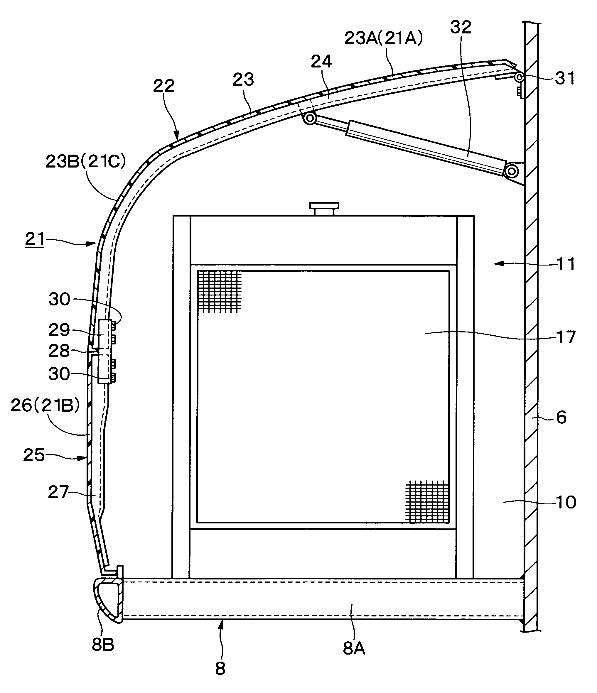
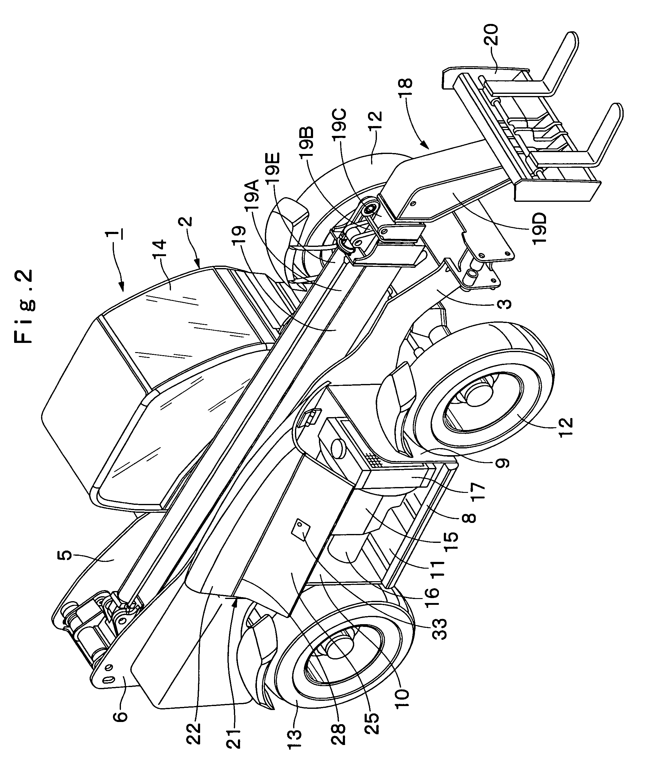
[0042] Referring first to FIGS. 1 through 7, there is shown the present invention. In these figures, the indicated at 1 is a lift truck which is arranged to serve as a working machine. The lift truck 1 is largely constituted of a wheeled automotive vehicular body 2 and a working device 18 as will be described later, for lifting up freight goods to a height from a ground level after self-propelling to a working site by use of the working device 18. The vehicular body 2 of the lift truck 1 is constituted of a frame 3, a cab 14, an engine 15, a heat-exchanger 17, and a device cover 21 and so forth as will be described later.
[0043] The indicated at 3 is the frame as a base of the vehicular body 2. As shown in FIG. 3, the frame 3 constitutes a strong support structure largely including a bottom plate 4 that is fabricated from a thick steel sheet and so forth, and extends in a direction from front to rear, vertical plates 5 and 6 on the right and left side, that are also fabricated from t...
second embodiment
[0092] However, in the device cover 41 the upper face separate cover element 22 is rotated in a direction from upper to lower, with the hinge member 31 as the center, and the side face separate cover element 25 is rotated in a direction from upper to lower, with the hinge member 44 as the center. With this structure, when the upper face separate cover element 22 and the side face separate cover element 25 are respectively set in the open position, the large working space can be secured around the devices accommodated in the device accommodation space 11, thus enhancing the workability of the inspection work for the devices.
[0093] Next, referring to FIG. 10 and FIG. 11, there is shown the third embodiment of the present invention. In the third embodiment, each separate cover element is separated at the position of the bent face of the device cover. In the following description of the second embodiment, those component parts which are identical with the counter parts in the foregoing...
third embodiment
[0109] However, the device cover 51 is constituted by the upper face separate cover element 52 and the side face separate cover element 55 which are separated at the position where the curvature of the bent face 51C becomes maximum. In addition, by connecting the bent face portion 53B of the plate member 53 constituting the upper face separate cover element 52 and the bent face portion 56A of the plate member 56 constituting the side face separate cover element 55 at the joint position 58, the bent face 51C of the device cover 51 having a protruding arcuate shape is formed.
[0110] With this structure, the curvature of the bent face portion 53B of the plate member 53 and the curvature of the bent face portion 56A of the plate member 56 can be made small. Therefore, the plate member 53 including the bent face portion 53B and the plate member 56 including the bent face portion 56A can easily be formed. As a result, this contributes to further reducing the manufacturing cost of the uppe...
PUM
 Abstract
Description
Claims
Application Information