Eureka AIR delivers breakthrough ideas for toughest innovation challenges, trusted by R&D personnel around the world.

Panel positioning device

Inactive Publication Date: 2007-07-26
CHUNGHWA PICTURE TUBES LTD
View PDF2 Cites 4 Cited by
  • Summary
  • Abstract
  • Description
  • Claims
  • Application Information

AI Technical Summary

Benefits of technology

[0006] In order to solve the problems mentioned above, the present invention provides a panel positioning device, which may be applied to fix panels with different size. As the panel arranged a plurality of printed wiring boards thereon, the positioning device may effectively overcome the difficulty and increase the stability and the quality of the fixing so as to prevent the scrap damage of the panel.
[0008] The sliding damage of the panel causing from the bad fixing is improved by providing a panel positioning device utilizes a fixed position mechanism and a vacuum suction system to effectively increase the stability of the panel and decrease the damage of the panel so as to improve the yield of the panel in the manufacturing process.

Problems solved by technology

Accordingly the requirement of the trend of large-scale and thin film Liquid crystal display panel (LCD panel), the difficulty of the related manufacturing technology becomes higher, such as the control of thin cell gap, stacking and aligning of panel, the movement and position of the large-scale panel, and the wide viewing problem.
As peeling off the polarizer, owing to the starting point not in the center portion of the panel, it easily causes the sliding or the movement of the panel to scrape the backside or cause the scrap damage.
However, there is generating an upward force as peeling off the polarizer and it easily causes the warped panel.
Besides, as the panel size is larger, the amount of PWB is corresponding increased and it increases the degree of the difficulty to position and fix the large-scale panel.

Method used


Image

  • Panel positioning device
  • Panel positioning device
  • Panel positioning device

Examples


Embodiment Construction

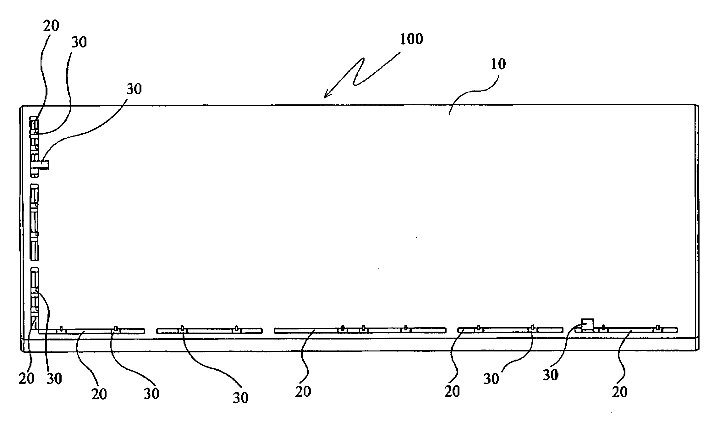
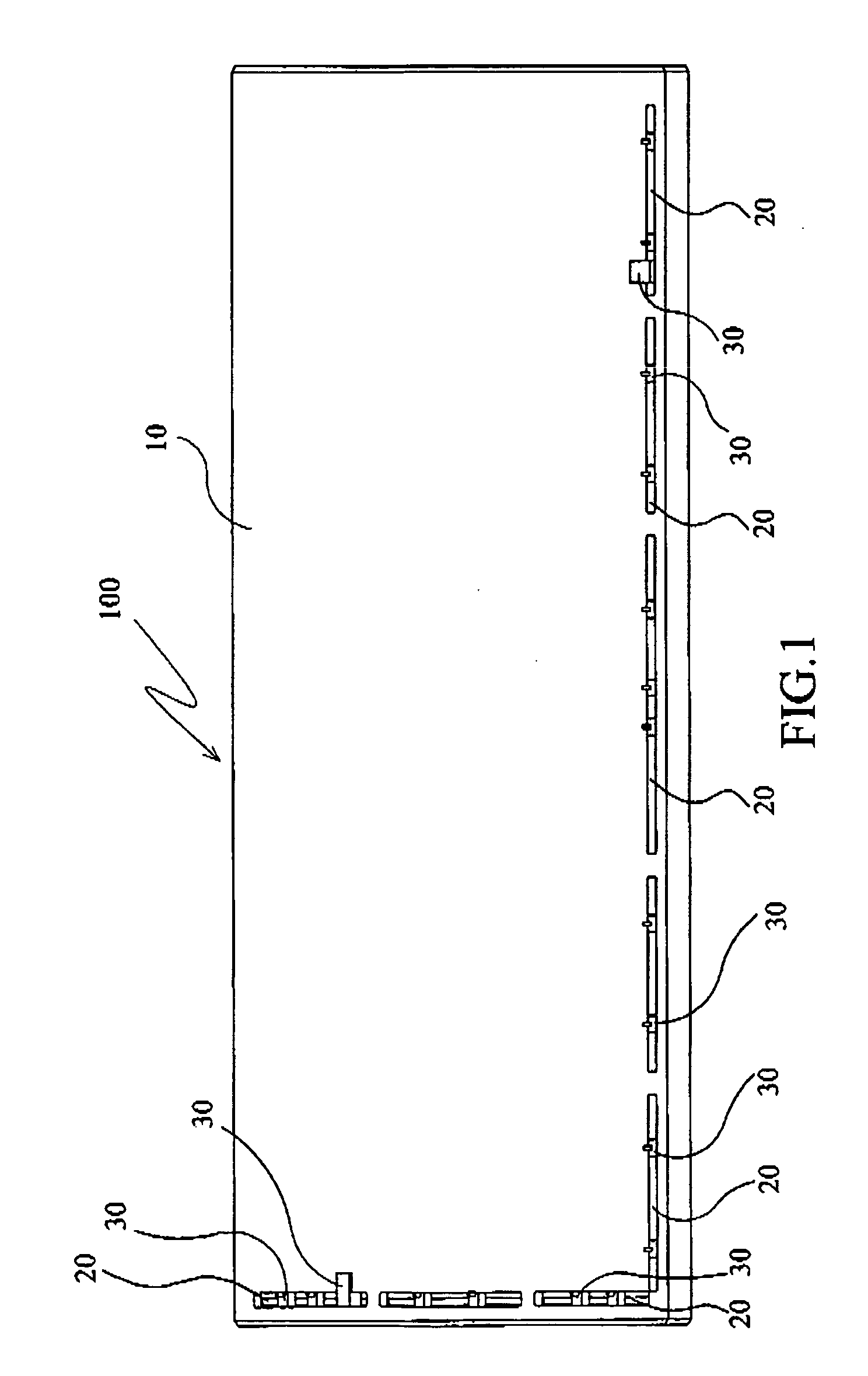
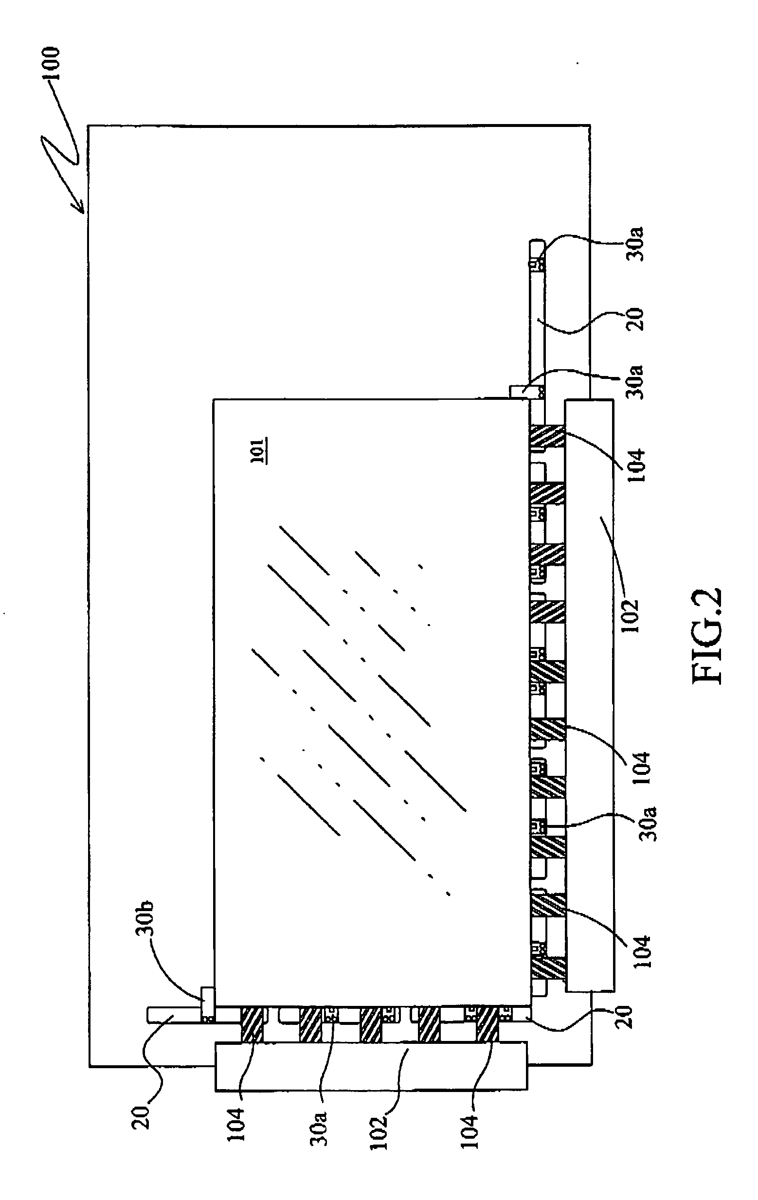
[0016]FIG. 1 is a perspective view illustrating the panel-positioning device in accordance with an embodiment of the present invention. In one embodiment, the panel-positioning device 100 includes a loader 10 for setting panel. There are a plurality of trenches 20 and a plurality of positioning elements 30 arranged on the loader 10. Wherein, each trench 20 is arranged at least one or more positioning elements 30 therein. Each positioning element 30 has a protruding portion protruded out the trench 20 for contacting and holding the panel. Each positioning element 30 may slide in the trench 20 to the corresponding location so as to enhance the flexibility for fixing panel. In an embodiment, the protruding portion is upward protruded. In another embodiment, the positioning element 30 is a L-shape profile and bulging out the trench 20, and wherein the protruding portion is extending to the direction of the loader 10 for contacting and holding a side edge of the panel.

[0017]FIG. 2 is a ...


PUM


Abstract

A panel positioning device utilizes fixed positioning elements and the trench so as the fixed positioning device may apply to the panel with different sizes. The positioning element may slide in the trench to the corresponding location and be fixed there. The location where the positioning element fixed in is a gap between the panel and the printed wiring board (PWB) or at an edge of the panel.

Description

BACKGROUND OF THE INVENTION [0001] 1. Field of the Invention [0002] The present invention generally relates to a panel positioning device, and more particularly relates to a display panel positioning device in the manufacturing of the display panel. [0003] 2. Description of the Prior Art [0004] Accordingly the requirement of the trend of large-scale and thin film Liquid crystal display panel (LCD panel), the difficulty of the related manufacturing technology becomes higher, such as the control of thin cell gap, stacking and aligning of panel, the movement and position of the large-scale panel, and the wide viewing problem. Wherein, the transportation and position of the panel is one of main reasons causing the scrap damage of the panel. Thus, the prevention of the scrape damage on the sliding panel may effectively improve the yield of the process. [0005] For example, the polarizer peeling off machine usually utilizes the block to fix and locate the panel keep to the side. Once the p...

Claims


Application Information

Patent Timeline
IPC IPC(8): B25B11/00
CPCB25B11/02B25B11/005
Inventor SHIU, CHIUAN-CHELEE, CHIH-CHIANGTENG, KUO-CHANG
Owner CHUNGHWA PICTURE TUBES LTD
Why Eureka
Eureka Blog
Learn More