
Guide loop for a safety belt

a safety belt and loop technology, applied in the direction of safety belts, pedestrian/occupant safety arrangements, vehicular safety arrangements, etc., can solve the problems of screw head of fixing screw only supporting the guide element with an extremely small overlap, fixing screw could pop out of the fixing hole of the guide element, and significant risk, so as to prevent free and unwanted rotation, and maximize the overlap of the bearing surface

Active Publication Date: 2007-07-26
AUTOLIV DEV AB
View PDF10 Cites 3 Cited by
  • Summary
  • Abstract
  • Description
  • Claims
  • Application Information

AI Technical Summary

Benefits of technology

[0007] This arrangement is particularly advantageous if the grooves are distributed evenly over the circumference of the boring, so that they assist in centering the fixing screw.
[0009] Therefore, without the use of additional components such as washers and without the need to manufacture a special type of screw, the guide loop proposed here maximizes the overlap of the bearing surface of the guide element with the screw head of the fixing screw, and therefore prevents the screw head from popping out of the fixing hole. It is also advantageous to affix the adapter onto the guide element to prevent free and unwanted rotation in relation to the guide element, without reducing the overlap of the guide element by the screw head.
[0010] A further embodiment of the guide loop formed according to the present invention provides that the fixing arms, when mounted to the guide element, form a circle with a slightly smaller internal diameter than the internal diameter of the boring. The advantage of this design is that the reduction of the cross-section of the fixing arms ensures that the fixing screw lies against the fixing arms without causing any noise.
[0011] Finally, it is possible to form the guide loop so that the fixing arms of the adapter are positioned relative to the adaptor such that when the adapter is mounted, an approximately constant slit height of the guide slit results. This also ensures that the adapter cannot rotate freely in relation to the guide element when mounted, and therefore a constant, preferably parallel geometry remains in the guide slit for belt guidance.

Problems solved by technology

A disadvantage of this solution is that the screw head of the fixing screw is only supported on the guide element with an extremely small overlap due to the cylindrical collar of the adapter located inside the fixing hole.
Because of this very slight overlap, there is significant risk that the fixing screw could pop out of the fixing hole of the guide elements in the presence of large loads, such as those occurring during a crash.
However, this leads to increased costs and parts count.

Method used


Image

  • Guide loop for a safety belt
  • Guide loop for a safety belt

Examples


Embodiment Construction

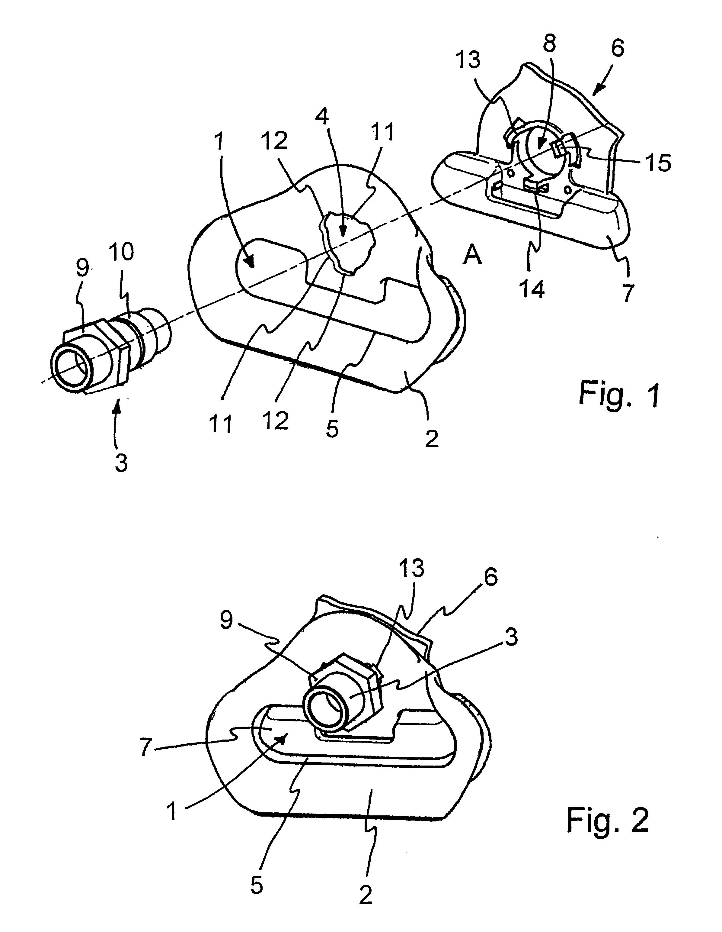
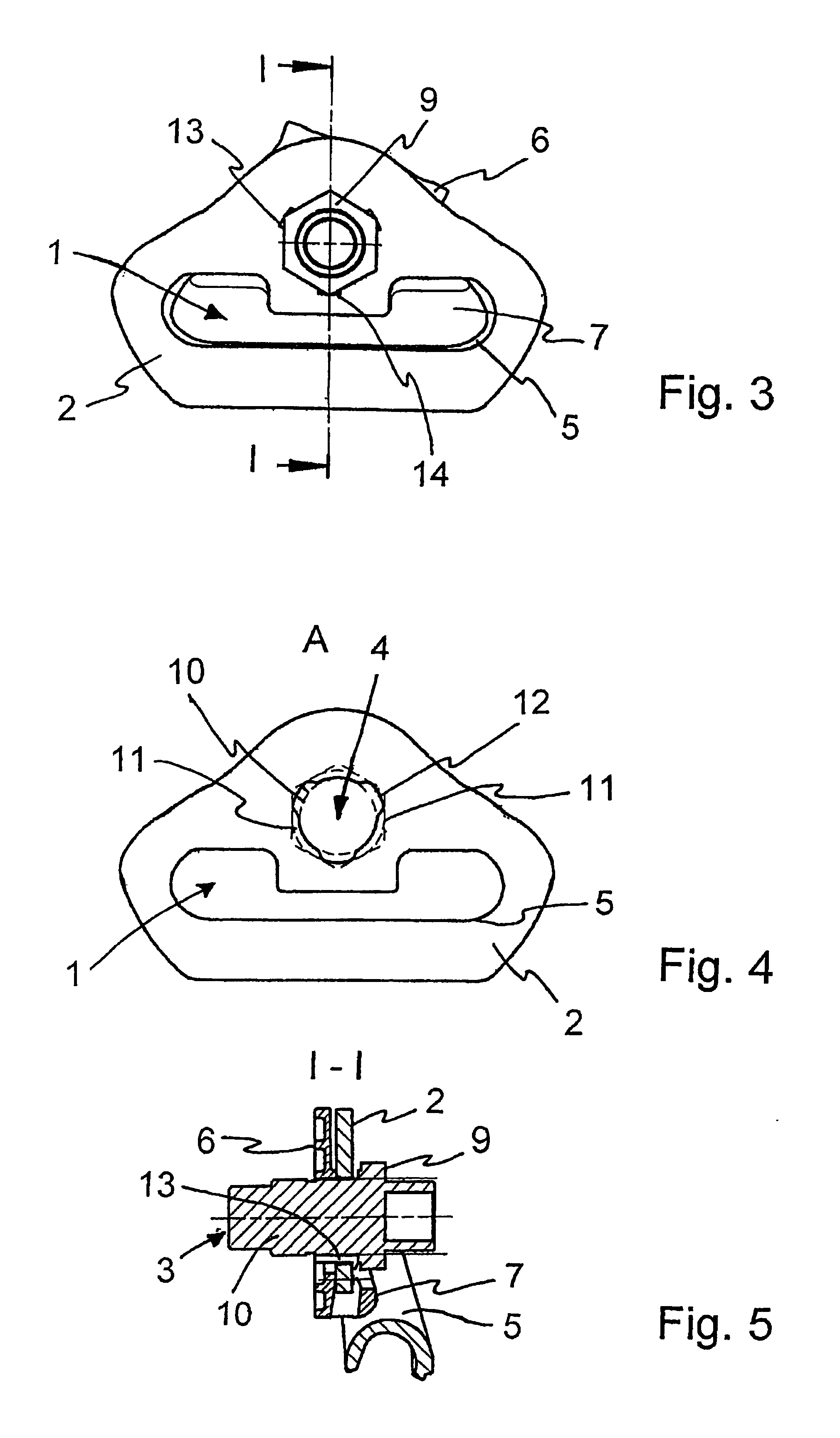
[0019] The guide loop for a safety belt according to the present invention is shown in an exploded view in FIG. 1. It includes a guide element 2, provided with a guide slit 1 for the safety belt (not shown), and also includes a fixing screw 3 and an adapter 6. The guide element 2 is fixed to a bearing component of the vehicle body (not shown), for example a vehicle pillar, by means of the fixing screw 3 inserted through a fixing hole in the form of a boring 4 in the guide element 2. For its part, the guide slit 1 includes a rounded running surface 5 for the safety belt, in order to ensure unhindered guidance of the same.

[0020] The guide element 2 is preferably manufactured as one piece of sheet steel by means of cold forming. Alternatively, it is formed as a steel plate moulded round with plastic.

[0021] Between the guide element 2 and the bearing component, the adapter 6, is provided and preferably manufactured of plastic by an injection moulding process. It includes a displacemen...


PUM


Abstract

A guide loop for a safety belt on motor vehicles, including a guide element provided with a guide slit for the safety belt, which is fixed to a vehicle by means of a fixing screw, and an adapter with a displacement body for limiting the slit width of the guide slit. The adapter is coupled to the inside of the fixing hole of the guide element and includes an opening penetrated by the fixing screw inserted through the fixing hole. The fixing hole of is formed by a boring, with a cross-section slightly larger than the external diameter of the screw in order to maximize the overlap between a bearing surface of the guide element and a head of the fixing screw. In addition, a number of grooves are distributed around the boring's circumference. When the adapter is mounted, the grooves accept fixing arms of the adapter.

Description

FIELD OF THE INVENTION [0001] The invention relates to a guide loop for a motor vehicle safety belt. BACKGROUND OF THE INVENTION [0002] A guide loop for a safety belt in a motor vehicle is described in U.S. Pat. No. 6,702,327 B2. It includes a guide element having a guide slit, also designated as a belt eye, for the safety belt. The guide element is in the form of a one-piece metal body of steel plate manufactured by the cold forming process, which is fixed to the vehicle body by means of a fixing screw through a fixing hole in a mounting surface. A plastic adapter is connected to the guide element, and includes a cylindrical collar for fixing of the same which can be inserted in the fixing hole and also a fixable displacement body at the upper limit of the belt eye for limiting the width of the guide slit. [0003] A disadvantage of this solution is that the screw head of the fixing screw is only supported on the guide element with an extremely small overlap due to the cylindrical co...

Claims


Application Information

Patent Timeline
IPC IPC(8): B60R22/00B60R22/24
CPCB60R22/24
Inventor CORD, HANS-JORGJANZEN, KNUT
Owner AUTOLIV DEV AB
Learn More