Eureka AIR delivers breakthrough ideas for toughest innovation challenges, trusted by R&D personnel around the world.

Piezoelectric/electrostrictive device

Inactive Publication Date: 2007-07-26
NGK INSULATORS LTD
View PDF9 Cites 8 Cited by
  • Summary
  • Abstract
  • Description
  • Claims
  • Application Information

AI Technical Summary

Benefits of technology

[0017]The present invention has been made taking the foregoing problems into consideration, it is an object of the present invention to provide a piezoelectric / electrostrictive device, which is capable of angularly displacing an object with its center of gravity moving a reduced distance, thereby reducing reactive forces generated in a region where the piezoelectric / electrostrictive device is fixed in position, so that the object can be actuated under an easy control and with an increased actuating frequency, i.e., an increased response speed.
[0055]When the rotor or an object to which the rotor is fixed is angularly displaced, because movement of the center of gravity of the rotor is small, reactive forces generated in a region at which the piezoelectric / electrostrictive device is fixed in place are small, so that the piezoelectric / electrostrictive device can actuate the object under an easy control with an increased actuating frequency and an increased response speed.
[0056]Therefore, the rotor can be controlled with high accuracy when it is angularly displaced. The piezoelectric / electrostrictive device is thus suitable for use in controlling an actuator for positional control of a hard disk drive (HDD). Additionally, the piezoelectric / electrostrictive device may be used successfully for controlling the angle of a small reflecting mirror, controlling the rotation of an antenna, controlling the θ-axis of an XY stage, or controlling the rotation of a manipulator.
[0057]Particularly, if the piezoelectric / electrostrictive device is used as an actuator for positioning the magnetic head of an HDD, then the slider can be angularly displaced with high accuracy, making it possible to eliminate or reduce the skew angle. Limitations on the configuration of the pole of the head are lessened for enabling greater freedom of design. Furthermore, inasmuch as interference with adjacent tracks is avoided, gaps, which typically have been provided in view of such interference, are unnecessary and the density of the tracks can be increased. Since the formation of side shields and inversely trapezoidal shapes is facilitated or made unnecessary, the piezoelectric / electrostrictive device for use as an actuator can be manufactured at a reduced cost.
[0058]Since the rotor can be translated at a constant skew angle, functions for performing track positioning and skew angle positioning can be realized by a single actuator. The HDD can thus be designed for higher performance and further be reduced in size.
[0059]As described above, the piezoelectric / electrostrictive device according to the present invention is capable of angularly displacing an object to which the rotor is secured. When the object is angularly displaced, any movement of the center of gravity of the rotor is small, and reactive forces generated in a region at which the piezoelectric / electrostrictive device is fixed in place are small. Thus, the piezoelectric / electrostrictive device can actuate the object under an easy control with an increased actuating frequency and an increased response speed.

Problems solved by technology

Conventional piezoelectric actuators are problematic in that the movable member thereof moves a small distance because the displacement of a piezoelectric / electrostrictive material as it is expanded or contracted is directly transferred to the movable member.
When the axial direction of the head / stack assembly deviates from the direction tangential to the tracks, since the vector of the air stream changes greatly, the lifted state of the magnetic head also changes greatly, and the gap by which the magnetic head is lifted off the magnetic disk becomes unstable.
As a result, it becomes difficult to stably utilize the electromagnetic conversion capability of the magnetic disk itself.
Perpendicular magnetic recording, in particular, tends to suffer a side write problem, depending on the configuration of the main magnetic pole.
HDDs based on the principles of perpendicular magnetic recording are subject to side write / side erase problems on the main magnetic pole of the write head, particularly if the skew angle is large.
When a surface of the main magnetic pole that is parallel to the track deviates from the direction tangential to the track upon recording of data, a magnetic flux leaving from the deviating surface of the main magnetic pole interferes with an adjacent track and writes an unwanted signal in the adjacent track, tending to weaken the magnetic field of the signal originally recorded in the adjacent track, or to weaken a signal read from the adjacent track, thereby causing a readout error.
However, it is very difficult to manufacture inversely trapezoidal main magnetic poles of stable dimensions and to impart highly accurate angles to such inversely trapezoidal main magnetic poles.
In addition, the discrete recording medium is highly costly to manufacture.

Method used


Image

  • Piezoelectric/electrostrictive device
  • Piezoelectric/electrostrictive device
  • Piezoelectric/electrostrictive device

Examples


first embodiment

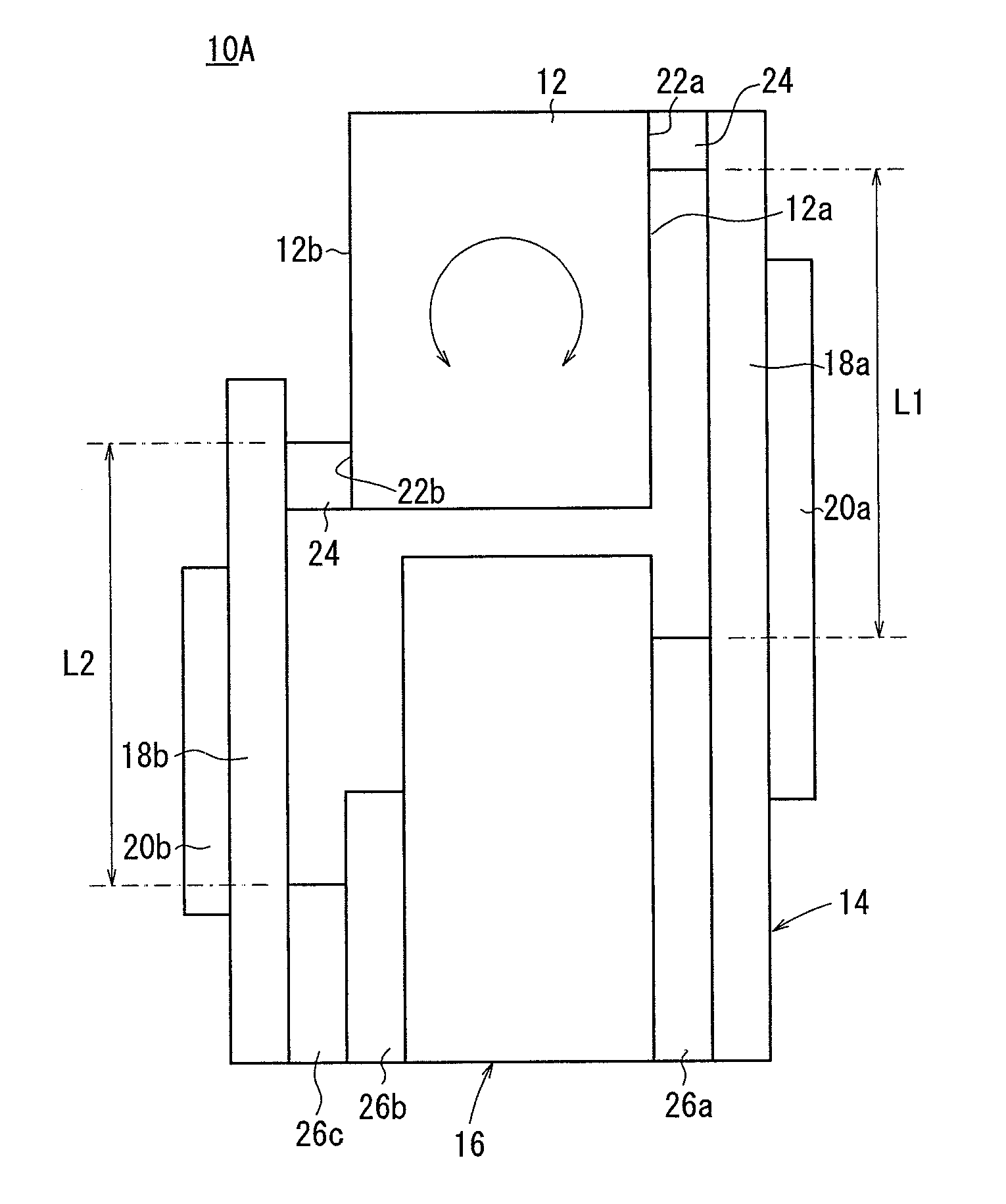
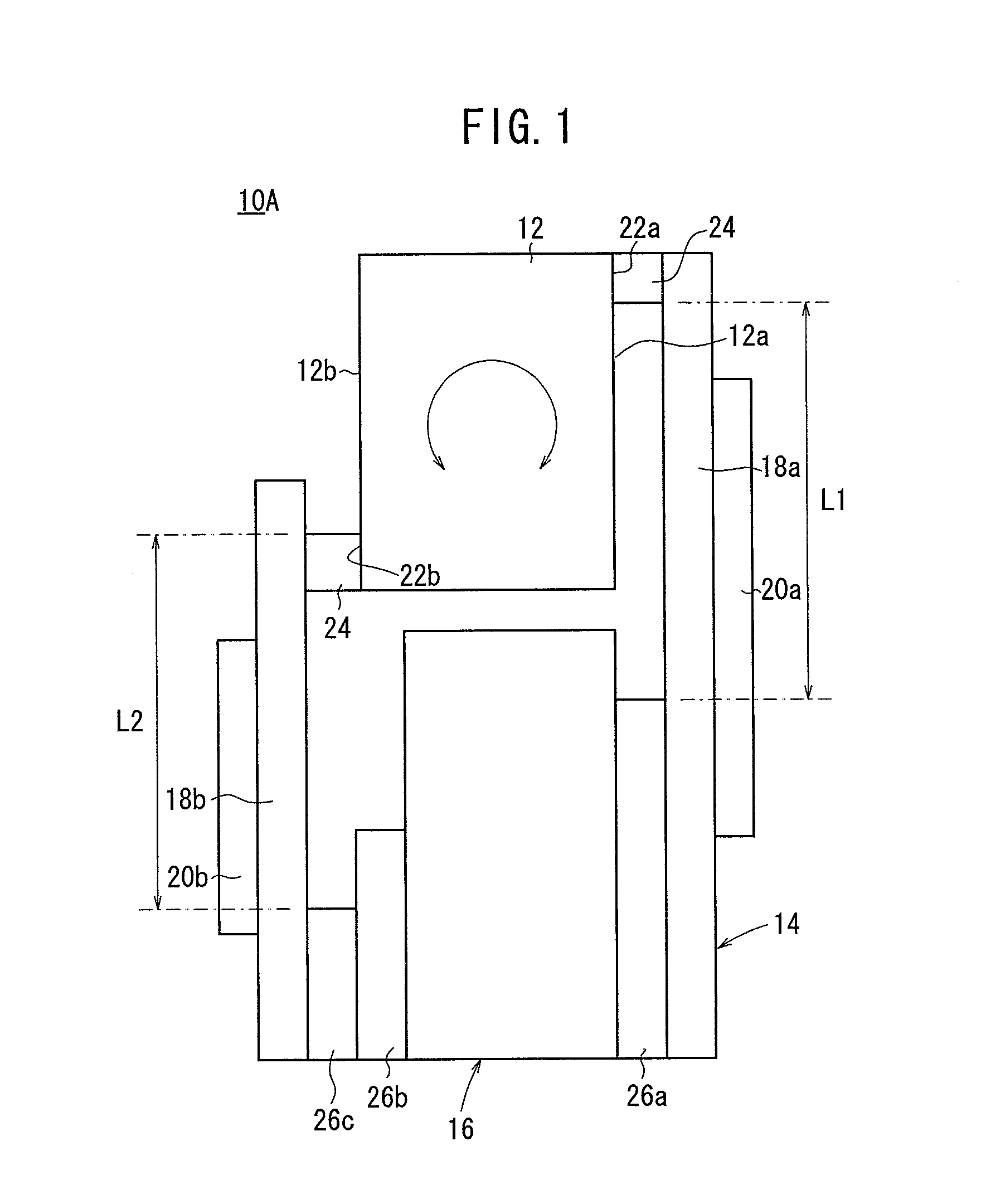
[0111]As shown in FIG. 1, a piezoelectric / electrostrictive device 10A according to the present invention (hereinafter referred to as a first piezoelectric / electrostrictive device 10A) comprises a rotor 12 substantially in the form of a rectangular parallelepiped, the rotor 12 having a pair of opposite surfaces 12a, 12b, and a rotary actuator 14 for angularly displacing the rotor 12. A slider, a sensor, a stage, or the like may be mounted on the rotor 12. Alternatively, the rotor 12 itself may serve as a slider, a stage, or the like.

[0112]The rotary actuator 14 includes a stationary member 16, a first vibratory plate 18a and a second vibratory plate 18b extending in one direction from opposite sides of the stationary member 16, a first piezoelectric / electrostrictive element 20a mounted on and extending from a side surface of the first vibratory plate 18a to the stationary member 16 for actuating the first vibratory plate 18a, and a second piezoelectric / electrostrictive element 20b mo...

second embodiment

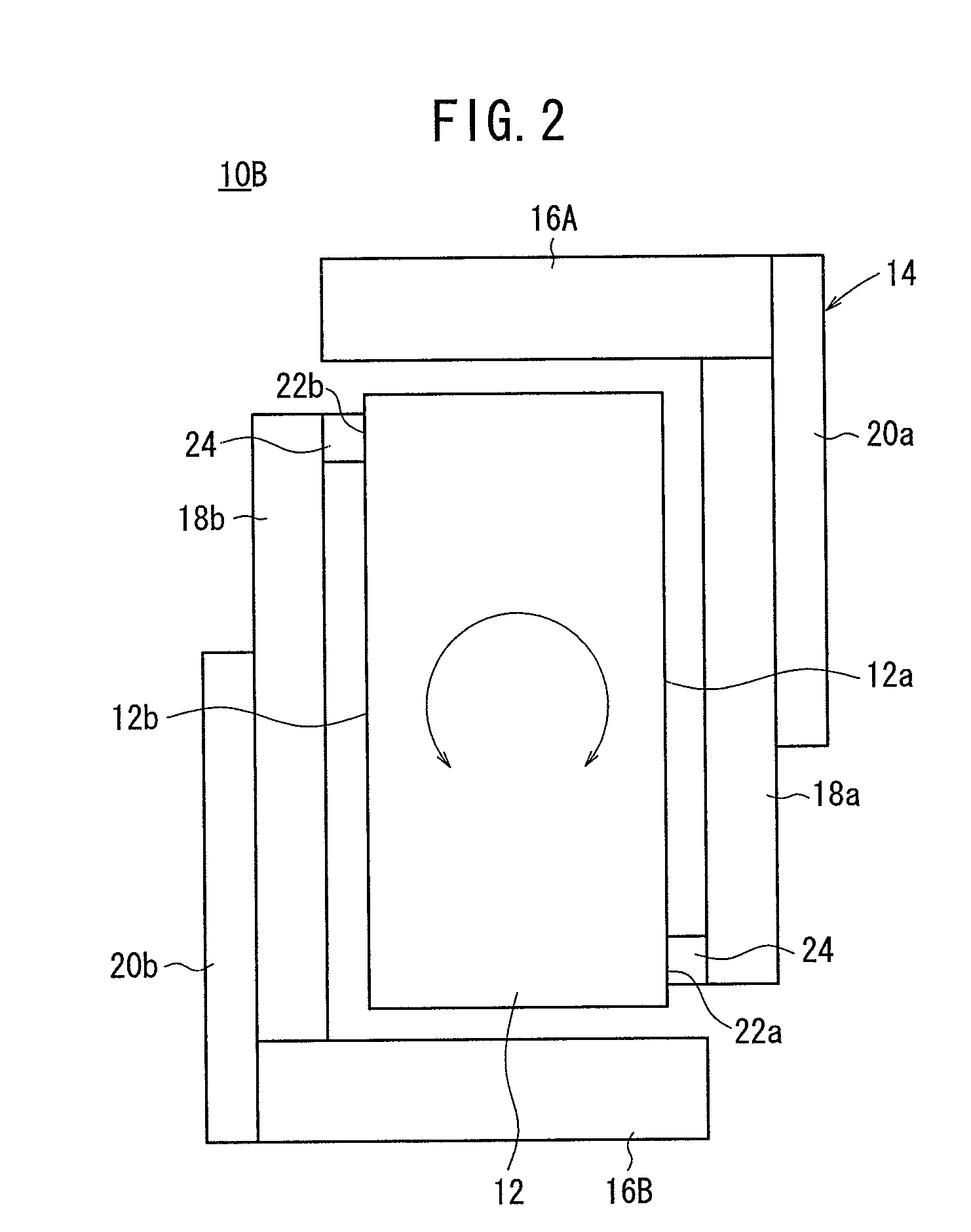
[0131]In the second embodiment shown in FIG. 2, the rotary actuator 14 is fixed to the rotor 12 at two locations. FIG. 3 shows a modified piezoelectric / electrostrictive device 10Ba. In FIG. 3, the first vibratory plate 18a has a first protrusion 28a mounted on a surface thereof which faces one surface 12a of the rotor 12 at a longitudinally central position, and the second vibratory plate 18b has a second protrusion 28b mounted on a surface thereof which faces another surface 12b of the rotor 12 at a longitudinally central position. The protrusion 28a is bonded to the one surface 12a of the rotor 12 by an adhesive 24, and the protrusion 28b is bonded to the other surface 12b of the rotor 12 by an adhesive 24.

[0132]The first stationary member 16A has a third protrusion 28c mounted on a surface thereof which faces the rotor 12 at a longitudinally central position thereof, and the second stationary member 16B has a fourth protrusion 28d mounted on a surface thereof which faces the roto...

seventh embodiment

[0216]The rotary actuator 14 is of a structure that is essentially the same as the rotary actuator 14 of the piezoelectric / electrostrictive device 10Gd according to the fourth modification of the seventh embodiment, but differs therefrom in that it comprises an integrally sintered assembly of laminated ceramic green sheets.

[0217]On an eleventh green sheet 88a, which serves as the first vibratory plate 18a and the second vibratory plate 18b, there are laminated and integrally sintered a twelfth green sheet 88b, which serves as the stationary member 16 and portions of the forty-first arm 84a and the forty-second arm 84b, thirteenth through fifteenth green sheets 88c through 88e, which serve as portions of the forty-first arm 84a and the forty-second arm 84b, and a sixteenth green sheet 88f, which serves as the movable member 80 with the rotor 12 mounted thereon. Each of the eleventh through sixteenth green sheets 88a through 88f comprises a single green sheet or a plurality of green s...


PUM


Abstract

A piezoelectric / electrostrictive device has a rotor substantially in the form of a rectangular parallelepiped, and a rotary actuator for angularly displacing the rotor 12. The rotary actuator includes a stationary member, a first vibratory plate and a second vibratory plate extending in one direction from opposite sides of the stationary member, a first piezoelectric / electrostrictive element for actuating the first vibratory plate, and a second piezoelectric / electrostrictive element for actuating the second vibratory plate. The rotor includes a pair of opposite surfaces, one of the surfaces having a first end secured to an end of the first vibratory plate and a second end, which is diagonally opposite to the first end, and which is secured to an end of the second vibratory plate.

Description

CROSS-REFERENCE TO RELATED APPLICATIONS[0001]This application is based upon and claims the benefit of priority from Patent Applications No. 2006-015684 filed on Jan. 24, 2006 and No. 2006-118159 filed on Apr. 21, 2006, in the Japanese Patent Office, of which the contents are incorporated herein by reference.BACKGROUND OF THE INVENTION[0002]1. Field of the Invention[0003]The present invention relates to a piezoelectric / electrostrictive device having a rotor which rotates based on displacement of a piezoelectric / electrostrictive element, or to a piezoelectric / electrostrictive device for detecting angular displacement of a rotor with a piezoelectric / electrostrictive element, for use in controlling an actuator for positional control of a hard disk drive (HDD), controlling the angle of a small reflecting mirror, controlling rotation of an antenna, controlling the θ-axis of an XY stage, and controlling rotation of a manipulator.[0004]2. Description of the Related Art[0005]Recently, optica...

Claims


Application Information

Patent Timeline
IPC IPC(8): H01L41/08
CPCH01L41/09H10N30/20
Inventor IKEDA, KOJISHIBATA, KAZUYOSHITAKAHASHI, NOBUO
Owner NGK INSULATORS LTD
Why Eureka
Eureka Blog
Learn More