Movable body driving device and automatic drawer equipment

a driving device and moving body technology, applied in the direction of door/window fittings, fittings, constructions, etc., can solve the problems of troublesome adjustment, high cost, troublesome adjustment, etc., and achieve the effect of simple structure and easy adjustmen

Inactive Publication Date: 2007-07-26
THK CO LTD
View PDF32 Cites 40 Cited by
  • Summary
  • Abstract
  • Description
  • Claims
  • Application Information

AI Technical Summary

Benefits of technology

[0005] The present invention has been made in view of the aforementioned problems and the first object of the present invention is to provide a movable body driving device which has simple structure, allows easy adjustment, and is capable of moving a movable body in a certain direction.
[0006] The second object of the present invention is to provide automatic drawer equipment which is capable of opening and closing a drawer just by providing a drawer driving mechanism with simple structure and which has premium quality. MEANS TO SOLVE THE PROBLEMS
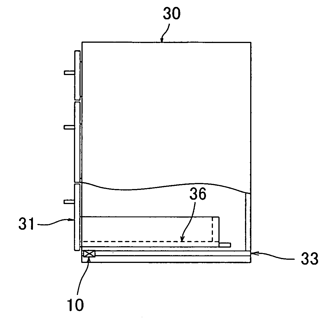
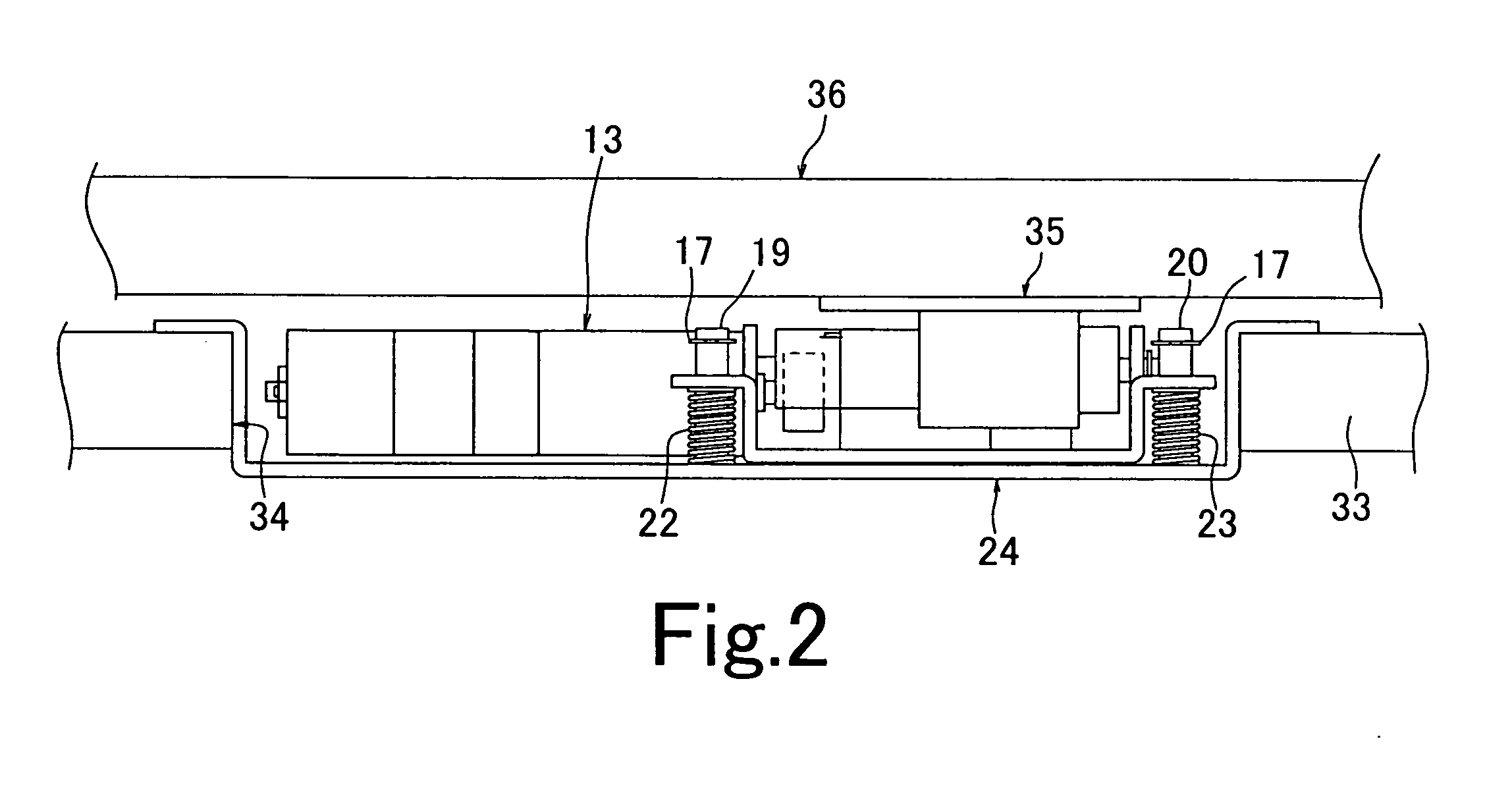
[0030] A concavity 34 for installing the movable body driving device 10 is formed in the front end portion of the bottom frame plate 33. The outer frame 24 of the movable body driving device 10 having the aforementioned arrangement is fitted in the concavity 34 and is fixed to the bottom frame plate 33 by screws or the like (not shown). In this state, the roller 12 of the movable body driving device 10 is pressed by the backing member 35 attached to the lower surface of the bottom plate 36 of the drawer 31 so that the movable body driving device 10 becomes to a state shown in FIG. 2. As the motor 13 of the movable body driving device 10 is driven from this state, the drawer 31 moves forward by fraction generated between the roller 12 and the backing member 35 so that the drawer 31 becomes to a state shown in FIG. 5. In this case, the drawer 31 has a projecting portion 31a on the rear end thereof so that the lower surface of the projecting portion 31a extends at the same level as the lower surface of the bottom plate 36 (see FIG. 4A). The backing member 35 is also attached to the lower surface of the projecting portion 31a so that the drawer 31 can move to such a position as to facilitate the taking out of things from the drawer. As shown in FIG. 4B, a backing member 35 which is integrally formed with the projecting portion 31a may be attached to the bottom plate 36. Since the roller 12 has no fixed contact, the automatic drawer device 30 can be adapted to a detachable drawer as shown in FIG. 6. The backing member 35 is not necessarily required when sufficient frictional force between the drawer and the roller 12 can be obtained or when wear of the drawer due to the contact by the roller 12 does not cause a problem.
[0047] The 
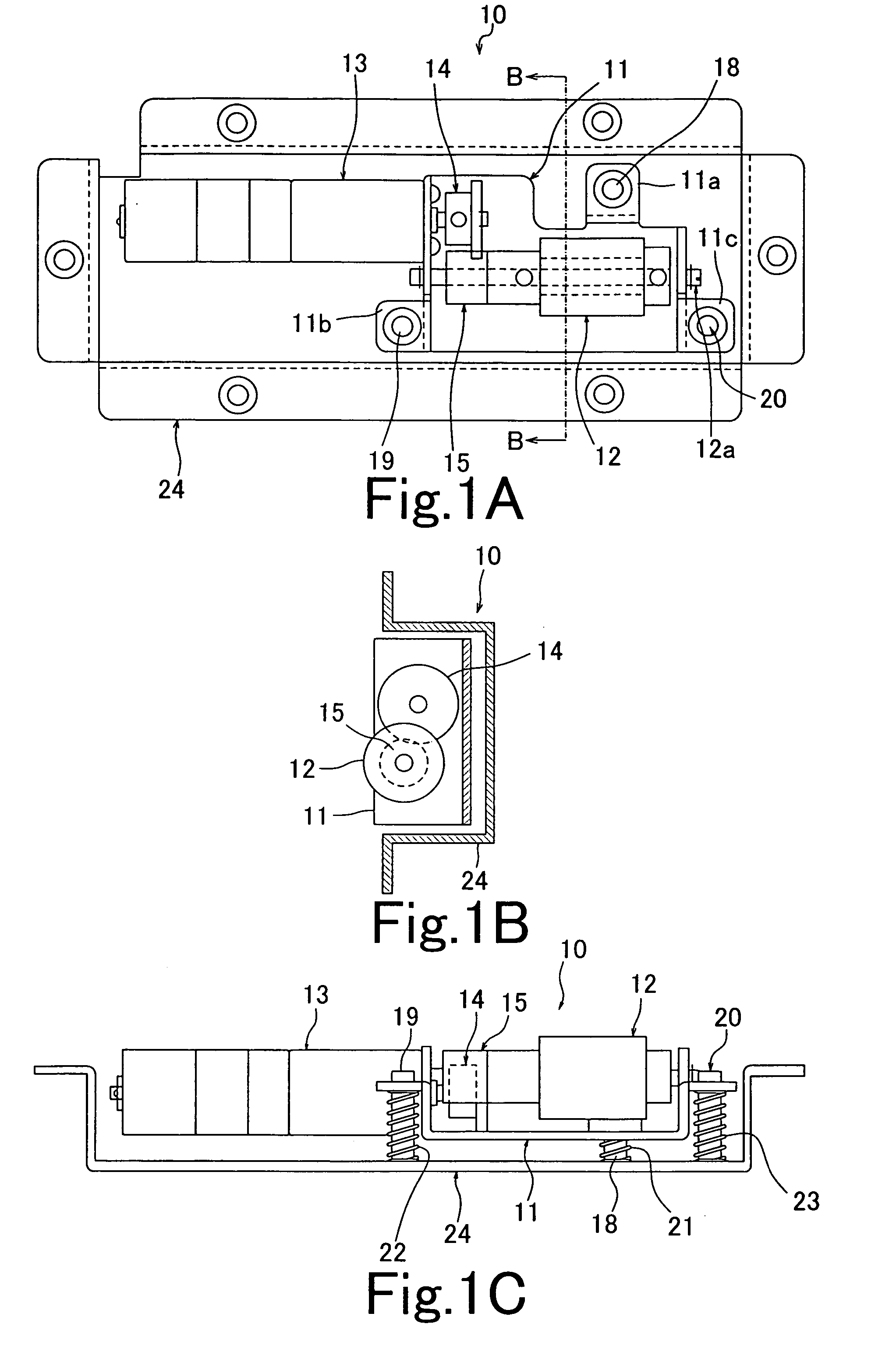
clutch means for allowing or interrupting the transmission of the rotational torque of the driving means to the rotary member is arranged between the rotary member and the driving means, whereby even when a motor such as a geared motor which does not rotate unless it is energized is used as the driving source of the driving means and when the motor is not energized or in a situation such as power outage where it is impossible to energize the motor, the connection between the rotary member and the driving means is cancelled by the clutch means so that the rotary member becomes free to rotate so as to allow a user to manually move the movable body smoothly.
[0058] Further, since the rotary member is a roller and is in contact with the drawer to move the drawer by frictional force between the roller and the drawer, the frictional force between the roller and the drawer can be adjusted by adjusting the force pressing the roller to the drawer by the elastic force of the elastic member. Therefore, the drawer can be moved by suitable driving force with the simple structure. Especially when the roller is in contact with the lower surface of the drawer bottom plate, the frictional force between the roller and the drawer depends on the weight of items accommodated in the drawer, that is, the force of pressing the roller by the drawer increases so that the frictional force also increases as the weight of items increases while the force of pressing the roller by the drawer decreases so the frictional force decreases as the weight of items decreases. Accordingly, the drawer can be opened and closed with suitable driving force. By the way, the drawer bottom plate may be deformed when heavy item(s) is accommodated in the drawer. Even when the bottom plate is deformed, the displacement due to the deformation can be absorbed by the function of the elastic member, whereby the roller is suitably in contact with the lower surface of the drawer bottom plate with suitable pressure.
[0060] Further, since the backing member for generating frictional force in connection with the roller is attached to the surface of the drawer with which the roller comes in contact, suitable frictional force can be generated between the roller and the drawer by selecting suitable material for the backing member according to the material forming the roller surface and wear of the surface of the drawer with which the roller comes in contact can be prevented.

Problems solved by technology

However, any of these has a problem that the mechanism thereof is complex so that troublesome adjustment among components is required and the cost is expensive.
These have also a problem that the adjustment among components and the mechanism for inclining the rails are complex so that troublesome adjustment is required.
Therefore, it is impossible or quite difficult for a user to open or close a drawer when the user has something with his or her both hands.
Accordingly, since a user must bow to take the heavy item in or out, it is hard work especially for a handicapped person or an elderly person to take the heavy item in or out.
However, there is still a problem that the adjustment among components and the mechanism for inclining the rails are complex so that troublesome adjustment is required.

Method used


Image

  • Movable body driving device and automatic drawer equipment
  • Movable body driving device and automatic drawer equipment
  • Movable body driving device and automatic drawer equipment

Examples


Embodiment Construction

[0026] Hereinafter, embodiments of the present invention will be described with reference to the attached drawings. Though the embodiments will be described with regard to cases of automatic drawer equipment and automatic door system, the movable body driving device according to the present Invention is not limited to those and can be adapted to a system for moving any of general movable bodies. FIGS. 1A-1C show the arrangement of a movable body driving device according to the present invention, wherein FIG. 1A is a plan view, FIG. 1B is a sectional view taken along an arrow B-B of FIG. 1A, and FIG. 1C is a frontal sectional view.

[0027] The movable body driving device 10 comprises a roller 12, as a rotary member supported by an inner frame 11 as a first supporting member in such a manner that the roller 12 is rotatable about a shaft 12a, and a motor 13. The rotational torque of the motor 13 is transmitted to the roller 12 via a motor gear 14 and an intermediate gear 15. That is, th...


PUM


Abstract

To provide a movable body driving device which has simple structure and is capable of moving a movable body in a certain direction and automatic drawer equipment. A movable body driving device is provided which comprises a roller 12 as a rotary member which is rotatably supported on an inner frame 11 as a supporting member and a motor 13 for rotating the roller 12. The roller 12 is brought in contact with the movable body, which is adapted to be movable in a certain direction, with predetermined force using elastic force of coil springs 21, 22, 23 as elastic members. The movable body is moved by frictional force between the movable body and the roller 12. Automatic drawer equipment employing the movable body driving device as its drawer driving mechanism is also provided.

Description

FIELD OF THE INVENTION [0001] The present invention relates to a movable body driving device for driving a movable body, such as a door or a drawer which is movable in a certain direction, in the moving direction and automatic drawer equipment in which a movable body driving device is employed as its drawer driving mechanism. BACKGROUND OF THE INVENTION [0002] As a method of driving a movable body, for example for reciprocating a door body of an automatic door system in certain directions to open and close the door, there are various driving methods such as a rack-and-pinion driving method, a wire driving method, a hydraulic driving method, and a linear-motor driving method. However, any of these has a problem that the mechanism thereof is complex so that troublesome adjustment among components is required and the cost is expensive. On the other hand, automatic drawer open-close operation has been conducted by a mechanical mechanism using an elastic member such as a spring or using ...

Claims


Application Information

Patent Timeline
Patent Type & Authority Applications(United States)
IPC IPC(8): A47B88/00E05F15/14A47B88/04
CPCA47B88/0414E05Y2201/214E05Y2201/22E05Y2201/232E05F15/635E05Y2201/462E05Y2201/674E05Y2201/722E05Y2900/20E05Y2201/434A47B88/457
Inventor HOSHIDE, KAORUSATO, AKIRASASAKI, SOICHI
Owner THK CO LTD
Why Eureka
Try Eureka