Eyelet for a radio frequency identification

a radio frequency identification and eyelet technology, applied in the direction of burglar alarm mechanical actuation, vortex flow apparatus, instruments, etc., can solve the problems of inability to avoid impact damage, poor durability of nonconductive materials such as plastics, and inability to resist external shocks, etc., to achieve stably fixed, simple assembly and stably fix the rfid module

Inactive Publication Date: 2007-07-26
RFCAMP
View PDF6 Cites 18 Cited by
  • Summary
  • Abstract
  • Description
  • Claims
  • Application Information

AI Technical Summary

Benefits of technology

[0007] To solve the problems described above, a housing formed of nonconductive material such as plastic may be used for protecting an RFID module and smooth communication between the RFID module and a reader-writer device. However, the durability of the nonconductive material such as plastic is poor against external shocks. A container firstly protecting an RFID module may be formed by using the nonconductive material but breakage caused by an impact cannot be avoided by using the structure of a conventional RFID tag.
[0008] The present invention provides an RFID tag which can firstly insulate an RFID module from the outside and simultaneously not disturb smooth communication between the RFID module and a reader-writer device and secondly protect the RFID module The present invention provides an RFID tag that can be minimized, simply installed, simply separated, and recycled to be economical.

Problems solved by technology

However, the durability of the nonconductive material such as plastic is poor against external shocks.
A container firstly protecting an RFID module may be formed by using the nonconductive material but breakage caused by an impact cannot be avoided by using the structure of a conventional RFID tag.

Method used


Image

  • Eyelet for a radio frequency identification
  • Eyelet for a radio frequency identification
  • Eyelet for a radio frequency identification

Examples


embodiment 1

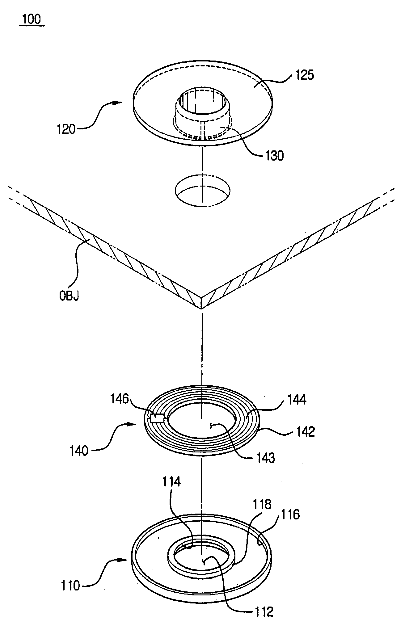
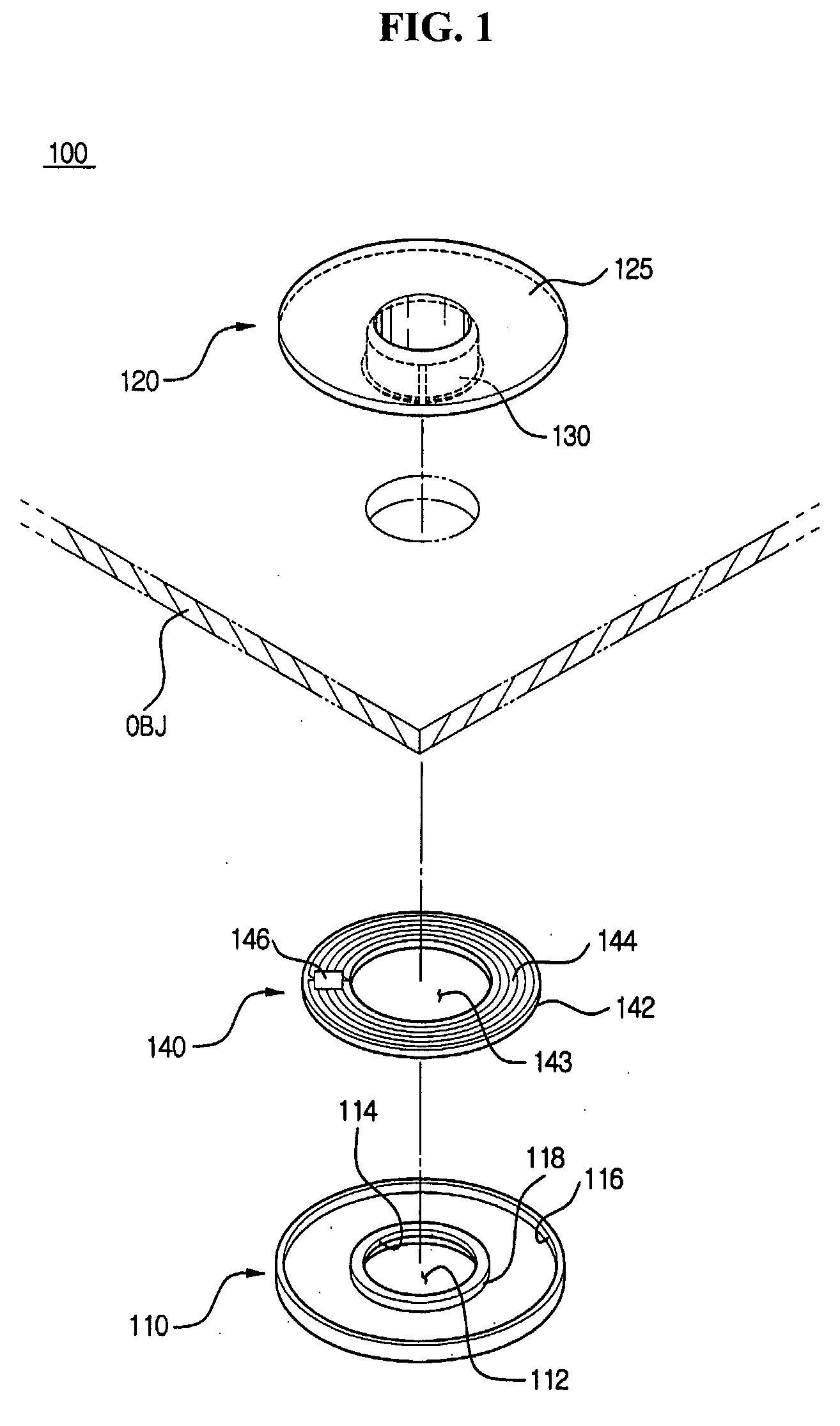
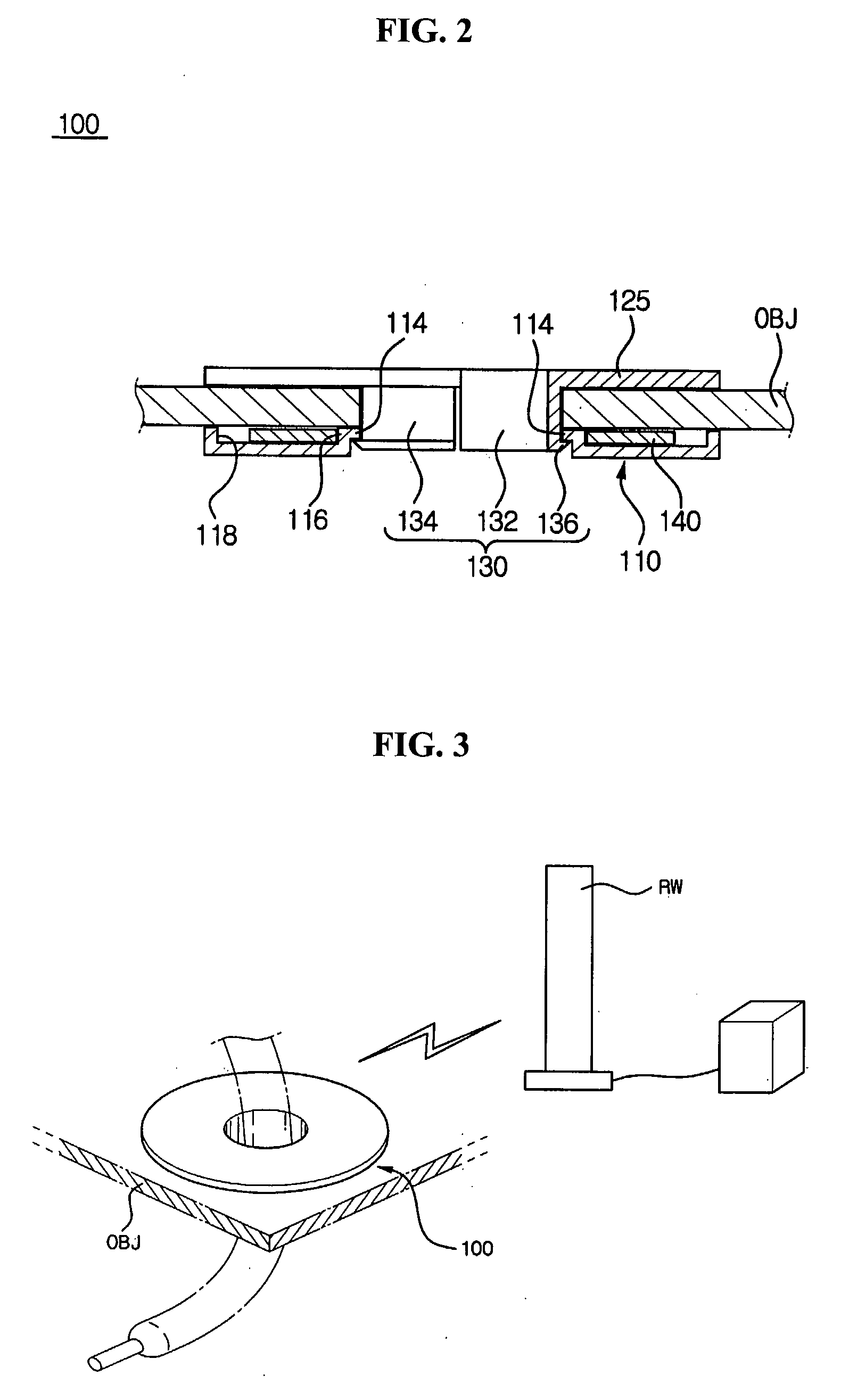
[0029]FIG. 1 is an exploded perspective view of an RFID eyelet according to a first embodiment of the present invention, and FIG. 2 is a partial cross-sectional view illustrating a state of engaging the RFID eyelet according to the first embodiment.

[0030] Referring to FIGS. 1 and 2, an RFID eyelet 100 according to the first embodiment includes an eyelet washer 110, an eyelet base 120, and an RFID module 140. An object OBJ and the RFID module 140 are interposed between the eyelet washer 110 and eyelet base 120 and adhered and fixed by interlock of the eyelet washer 110 and eyelet base 120.

[0031] The eyelet washer 110 is formed in a shape of a ring, and a washer hole 112 is formed in the center of the eyelet washer 110. A locker 114 is formed peripherally on the inside of the washer hole 112. Also, on the top side of the eyelet washer 110, where faces the object OBJ, an external flange 116 and internal flange 118 are formed around the outer circumference and inner circumference of t...

embodiment 2

[0043]FIG. 5 is an exploded side view of an RFID eyelet according to a second embodiment of the present invention, and FIG. 6 is a partial cross-sectional view illustrating a state of coupling the RFID eyelet according to the second embodiment.

[0044] Referring to FIGS. 5 and 6, the RFID eyelet according to the second embodiment includes an eyelet washer 310, an eyelet base 320, and an RFID module 340. An object OBJ and the RFID module 340 are interposed between the eyelet washer 310 and the eyelet base 320 and adhered and fixed by interlock of the eyelet washer 310 and eyelet base 320.

[0045] As the same as the first embodiment, the eyelet washer 310 is formed in a shape of a circle, and a washer hole 312 and a locker 314 are formed in the center of the eyelet washer 310. A plurality of projections of the locker 314 are formed to be faced with the eyelet base 320 as a slanted projection 336 of the eyelet base 320.

[0046] An external flange 316 and internal flange 318 are formed aro...

embodiment 3

[0051]FIG. 7 is an exploded side view of an RFID eyelet according to a third embodiment of the present invention, and FIG. 8 is a bottom view illustrating a state of coupling the RFID eyelet according to the third embodiment.

[0052] Referring to FIGS. 7 and 8, the RFID eyelet according to the third embodiment includes an eyelet washer 410, an eyelet base 420, and an RFID module 440. The object OBJ and the RFID module 440 are interposed between the eyelet washer 410 and eyelet base 420 and closely adhered and fixed by interlock between the eyelet washer 410 and eyelet base 420.

[0053] Similarly to the first embodiment, the eyelet washer 410 is formed in a circle shape, and a washer hole 412 and locker section 414 are formed in the center of the eyelet washer 410. Only, eyelet washer 410 is partially cut opened, and the washer hole 412 has an opening opened as the section. Also, the locker section 414 is formed along the inner circumference of the washer hole 412 in response to a fixi...


PUM


Abstract

Provided is an RED eyelet performing non-contact identification function. The RFID eyelet includes an eyelet washer and eyelet base composed of nonconductive material, and an RED module is interposed between the eyelet washer and eyelet base. The RFID eyelet contains the RFID module in nonconductive material, thereby performing smooth electromagnetic wave communication without disturbance, and the eyelet base is simply coupled. with the eyelet washer by using a slanted projection formed in the eyelet base and a locker formed in the eyelet washer. Also, the RED module can be easily installed by using an internal flange or external flange formed in the inside of the eyelet base or eyelet washer, thereby having a merit of mass production.

Description

TECHNICAL FIELD [0001] The present invention relates to a tag using Radio Frequency Identification (RFID) technology, and more particularly, to a tag for RFID, which can be applied regardless of the sort and form of an object requiring identification and be used for multiuse. BACKGROUND ART [0002] An RFID tag generally composed of an antenna and an IC chip transmits and receives predetermined data from an external reading unit. The RFID tag is called as a transponder. The RFID tag can transmit and receive required data from an external reader-writer device according to a non-contact method. For example, the RFID tag is used in managing products because of the characteristic of the non-contact method and is variously used for IC cards for payment or passes. The RFID tag can transmit and receive data with a reader-writer device by using the non-contact method. According to some method, since the RFID tag generates a electric power by itself with receiving high frequency from a reader-...

Claims


Application Information

Patent Timeline
Patent Type & Authority Applications(United States)
IPC IPC(8): G08B13/14G06K19/07G06K19/04
CPCG06K19/04G06K19/07762G06K19/07758G06K19/047A61L9/127A61L9/145A61L9/22B04C9/00
Inventor RYU, JAE HYUNG
Owner RFCAMP
Why Eureka
Try Eureka