Plasma display panel apparatus and method of driving the same

Inactive Publication Date: 2007-07-26
PANASONIC CORP
View PDF8 Cites 16 Cited by
  • Summary
  • Abstract
  • Description
  • Claims
  • Application Information

AI Technical Summary

Benefits of technology

[0008] In view of the above problem, an object of the present invention is to provide a PDP apparatus having a high display quality and a meth

Problems solved by technology

This incurs deterioration of the display quality, and therefore, various attempts from an aspect of driving methods have been made in order to improve such a problem.
In general, power consumption decreases when a dark screen image is displayed, because an area of the screen imag

Method used


Image

  • Plasma display panel apparatus and method of driving the same
  • Plasma display panel apparatus and method of driving the same
  • Plasma display panel apparatus and method of driving the same

Examples


first embodiment

1. Structure of PDP Apparatus

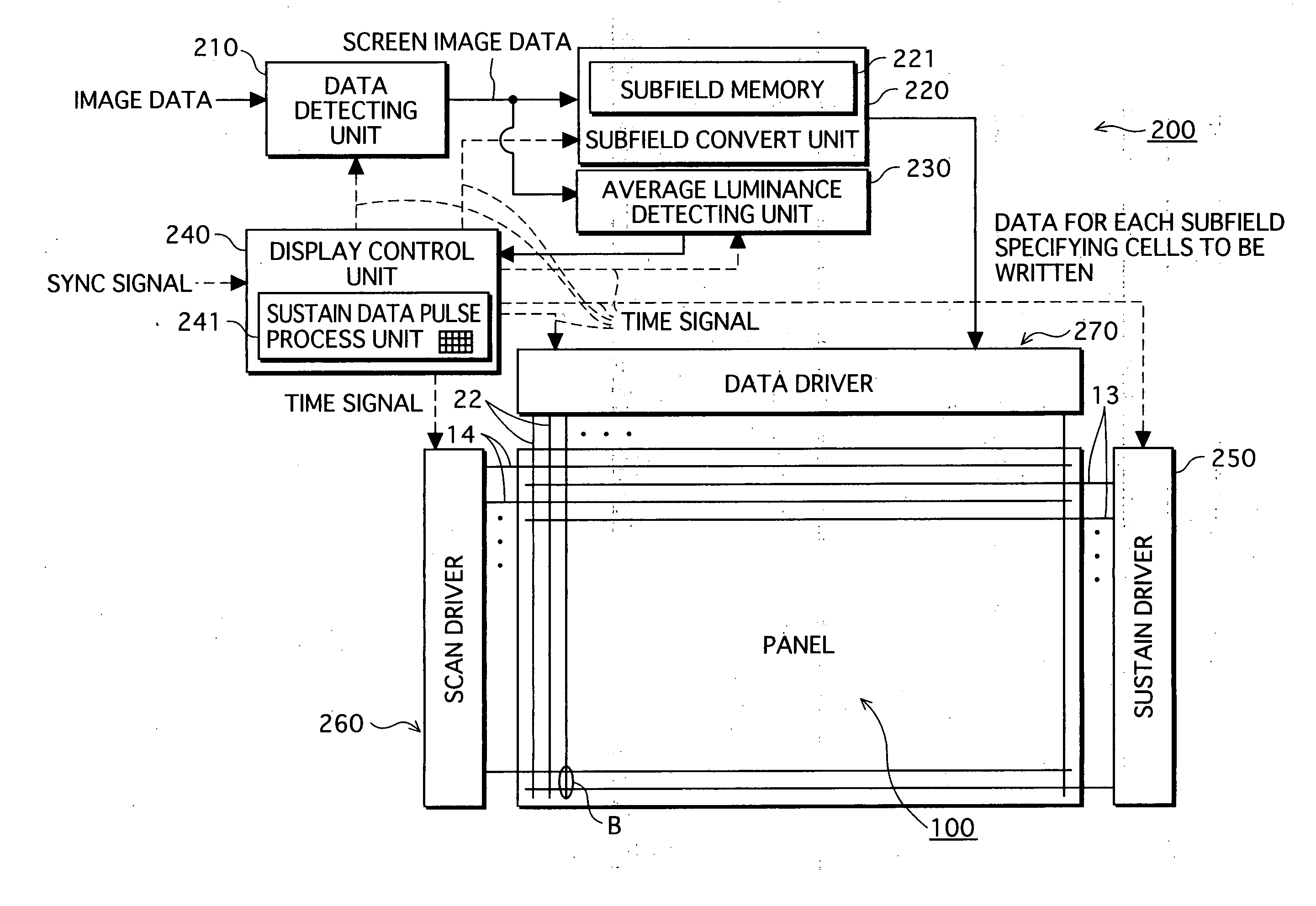
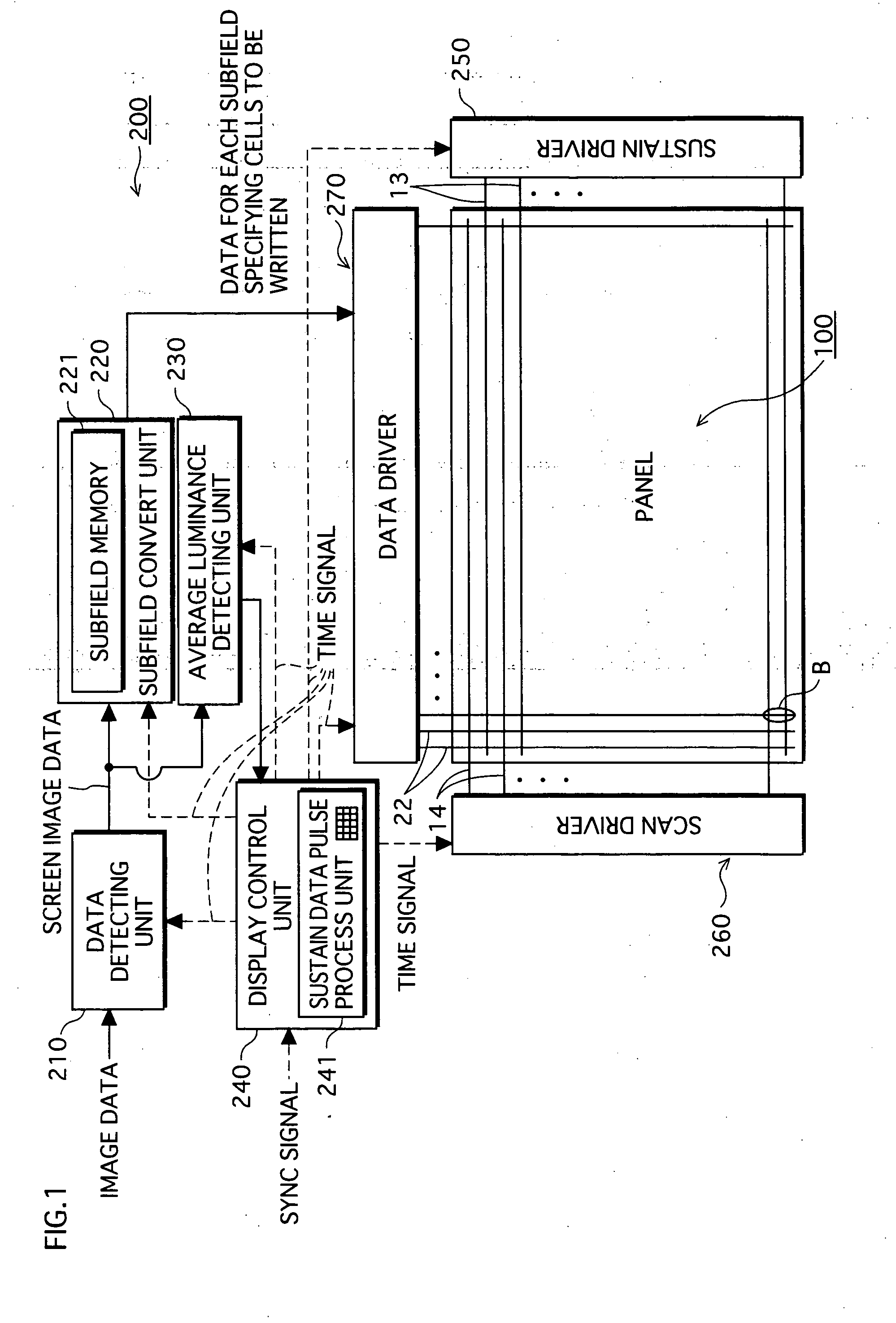
[0041] An overall structure of the PDP apparatus is described with reference to FIG. 1. FIG. 1 is a block diagram illustrating the structure of the PDP apparatus according to a first embodiment.

[0042] As shown in FIG. 1, the PDP apparatus according to the present embodiment includes a panel device 100 for displaying images and a drive device 200 for driving the panel to display the images using a field time-sharing grayscale display method.

1-1. Structure of Panel Device 100

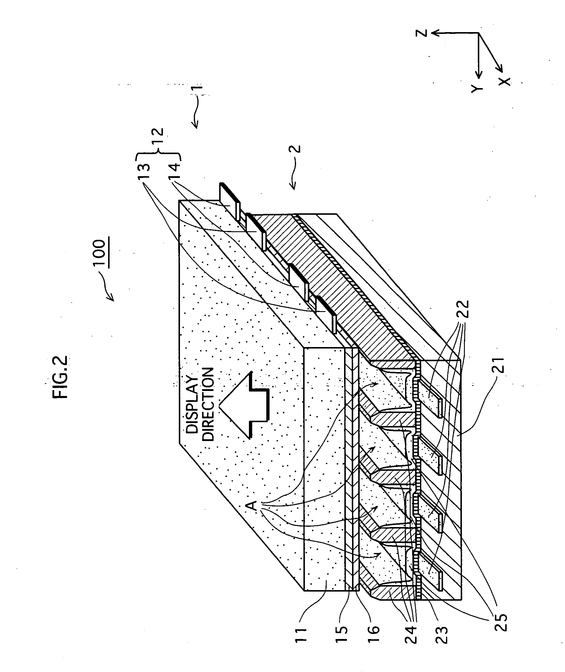
[0043] The following describes a structure of the panel device 100 in the PDP apparatus according to the present embodiment, with reference to the FIGS. 2 and 3. FIG. 2 is a perspective (partially sectional) view illustrating a main part of the panel device 100, and FIG. 3 is a plain view illustrating the panel device 100.

[0044] As shown in FIG. 2, the pane device 100 includes a sealed container structured by a front panel 1 and a back panel 2 facing each other with a space there...

second embodiment

[0104] Next, the following describes a method of driving the PDP apparatus according to a second embodiment with reference to FIGS. 11, 12, and 13. An outline of a structure of the PDP apparatus according to the present embodiment is the same as the PDP apparatus according to the first embodiment, and therefore not explained here. In the following, only the method of driving and controlling the best sustain data pulse process unit.

[0105] In the first embodiment, the sustain data pulse 314 have the constant pulse width, and the fall start time is controlled by changing the rise start time of the sustain data pulse 314. The inventors of the present invention further found that, when displaying the dark screen image, it is possible to modulate the luminance in the PDP apparatus by controlling the fall start times of the pulses in the sustain data pulse 314, thereby controlling the luminance in the PDP apparatus.

[0106] In order to realize this, in the present embodiment, the fall star...

third embodiment

[0125] In the above first and second embodiments, the dark screen image is displayed vividly with high contrast by controlling the fall start times of the sustain data pulses 314 and 414 according to the average luminance. The inventors further found that it is also possible to modulate the luminance in the PDP apparatus by controlling a voltage value of the sustain data pulse, and by this, the dark screen image can be displayed vividly with high contrast.

[0126] Thus, in the present embodiment, the voltage is set according to the average luminance, while the fall start times are fixed regardless of the average luminance.

[0127] An explanation in the present embodiment mainly focuses on differences between the present embodiment and the first embodiment, i.e. waveforms of the sustain data pulse 514, the method of controlling the best sustain data pulse process unit, and the structure of the-data driver.

1. Sustain Data Pulse 514 Applied to Dat Electrodes 22 During Sustain Period 31...


PUM


Abstract

The present invention aims to provide a PDP apparatus, where a sustain data pulse is applied to data electrodes during a sustain period, having high display quality,and capable of displaying a dark screen image vividly with high contrast without using an error diffusion method, as well as to provide a method of driving the PDP apparatus. In order to achieve the above object, the method of driving the PDP apparatus according to the present invention, during the sustain period, detects an average luminance of a screen image to be displayed, and sets a voltage waveform of a sustain data pulse to be applied to the data electrodes according to the detected average luminance, thereby modulating a luminance of the screen image.

Description

TECHNICAL FIELD [0001] The present invention relates to a plasma display panel apparatus and a method of driving the same, and more specifically, it relates to a technique of driving the apparatus that improves qualities of a screen image. BACKGROUND ART [0002] Plasma display panel (PDP) apparatuses have relative ease in increasing a screen size, in comparison with cathode ray tube (CRT) display apparatuses that are currently most commonly used. Such PDP apparatuses attract attentions as image display apparatuses suitable for hi-vision broadcasting. The PDP apparatuses are typically classified into an alternating current (AC) type and a direct current (DC) type. At present, AC-type PDP apparatuses (hereinafter referred to simply as PDP apparatuses) form a mainstream because of their superiority in a variety of aspects such as reliability and display quality. [0003] Generally, with the PDP apparatuses, an image for one screen (a screen image) becomes unclear with low luminance, i.e. ...

Claims


Application Information

Patent Timeline
IPC IPC(8): G09G3/28G09G3/294
CPCG09G3/2942G09G2360/16G09G2320/066G09G2320/0271G09G3/291G09G3/296
Inventor HASHIMOTO, SHINICHIROKITAGAWA, MASATOSHIMORITA, YUKIHIROKOSUGI, NAOKI
Owner PANASONIC CORP
Why Eureka
Try Eureka