
Positive displacement motor/progressive cavity pump

Active Publication Date: 2007-07-26
NAT OILWELL DHT
View PDF7 Cites 20 Cited by
  • Summary
  • Abstract
  • Description
  • Claims
  • Application Information

AI Technical Summary

Benefits of technology

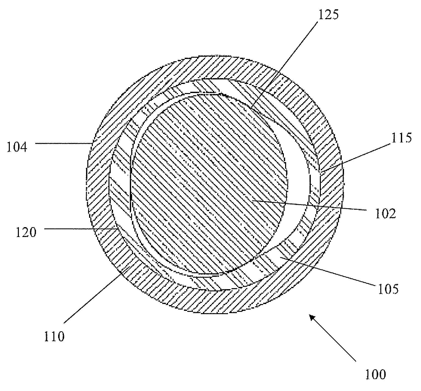
[0013]A rotor-stator assembly for a progressive cavity pump and / or positive displacement motor is disclosed, wherein the rotor-stator assembly permits reduced heat generation due to centrifugal forces caused by nutation of the rotor within the stator, heat retention by the stator's elastomeric liner, if present, and manufacturing costs for the stator housing while retaining the ability of the stator to assume various lobe configurations.

Problems solved by technology

Rotor-stator assembly failures may occur due to the destruction of the stator elastomer.
Mechanical failure of the elastomer occurs when it is overloaded beyond its stress and strain limits, such as may be caused by a high compression fit between the rotor and stator.
Thermal failure of the elastomer occurs when the temperature of the elastomer exceeds its rated temperature for a prolonged period.
Even for shorter periods of time, increasing elastomer temperature causes elastomer physical properties to weaken, resulting in a shortened elastomer life.
The combined effects of interference, centrifugal forces, and sliding or rubbing of the rotor within the stator generate heat within the stator elastomer, causing the temperature of the elastomer to rise.
Heat from these mechanisms—interference, centrifugal forces, hysteresis, and other downhole sources—may cause the elastomer temperature to rise above its rated temperature, resulting in shortened elastomer life or its failure.
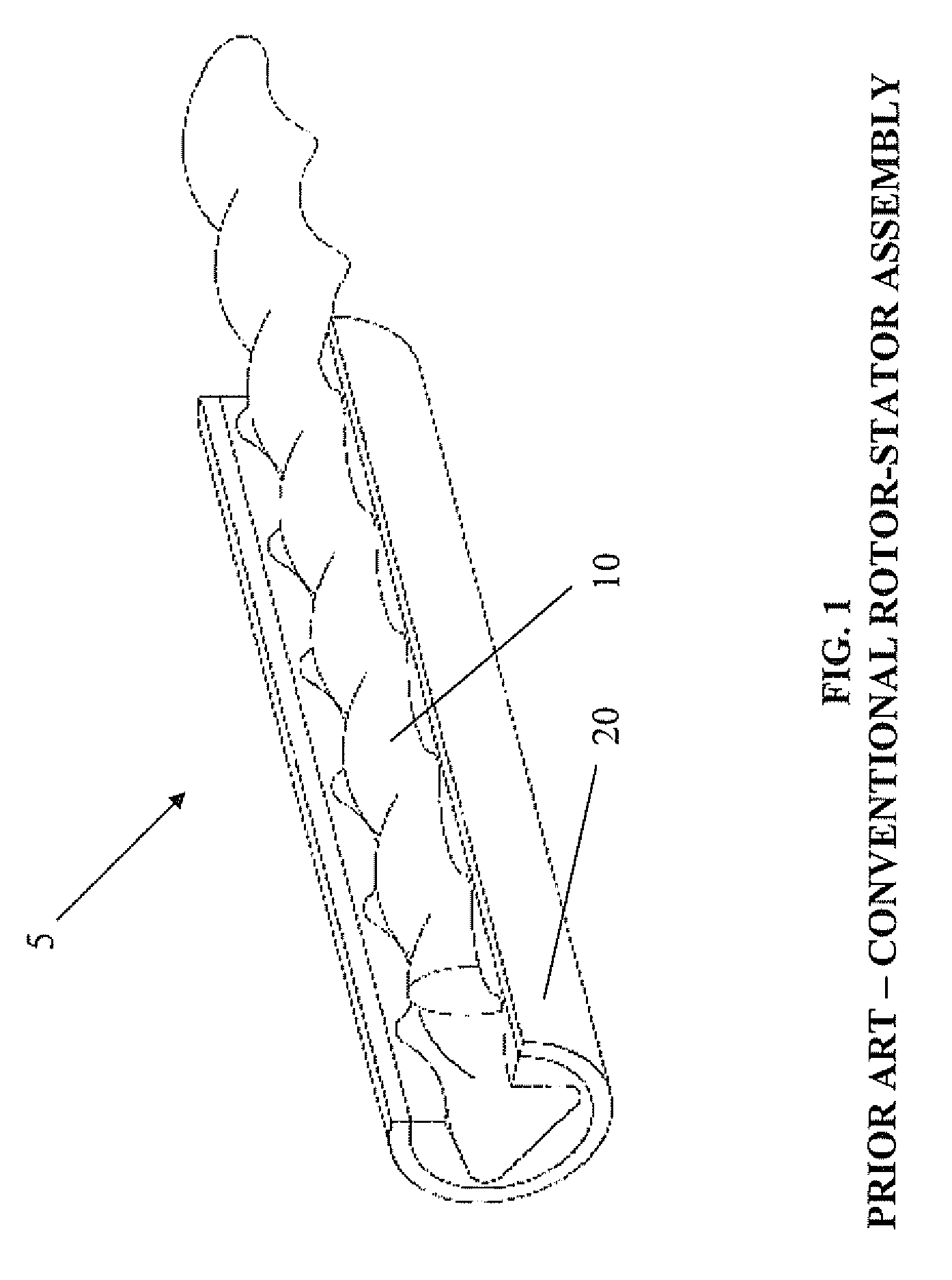
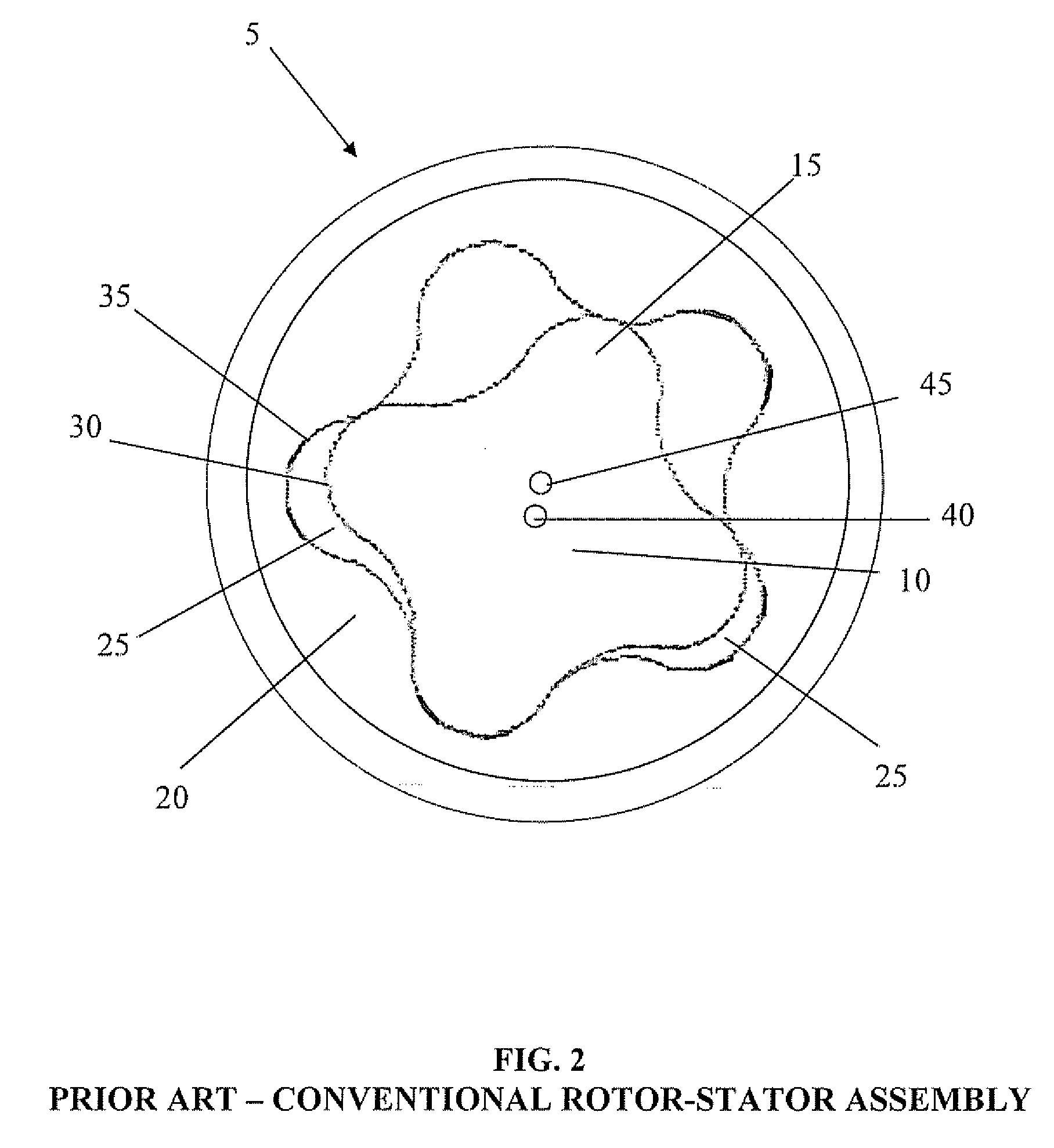
This conventional rotor-stator design and others similar to it are prone to high centrifugal forces as the rotor 55 turns within the stator 60 due to the high eccentricity of the rotor-stator assembly 50.
Additionally, the elastomer design itself inhibits the ability of the elastomer 62 to dissipate heat due to the liner thickness and its relatively low thermal conductivity.
However, this design modification does not directly address the sources of that heat - the centrifugal forces resulting from nutation of the rotor within the stator and the eccentricity of the rotor-stator assembly.
Moreover, this design configuration adds manufacturing complexity, and therefore expense, due to the non-cylindrical inner surface or shape of the stator housing 80.
Still further, this design configuration also limits the range of applications for which the housing 80 may be used.

Method used


Image

  • Positive displacement motor/progressive cavity pump
  • Positive displacement motor/progressive cavity pump
  • Positive displacement motor/progressive cavity pump

Examples


Embodiment Construction

[0030]Various embodiments of a rotor-stator assembly for a positive displacement motor and / or a progressive cavity pump that offer the potential to reduce heat generation caused by centrifugal forces resulting from nutation of the rotor within the stator, heat retention by the stator elastomeric liner, if present, and manufacturing costs while retaining design configuration flexibility, will now be described with reference to the accompanying drawings. Like reference numerals are used for like features throughout the several views. There are shown in the drawings, and herein will be described in detail, specific embodiments of the rotor-stator assembly with the understanding that this disclosure is representative only and is not intended to limit the invention to those embodiments illustrated and described herein. The embodiments of the rotor-stator assembly disclosed herein may be used in any type of positive displacement motor (PDM) or progressive cavity pump (PCP). It is to be fu...


PUM


Abstract

Disclosed is a progressive cavity device. In some embodiments, the device includes a stator with an inner surface having a number of lobes and a rotor disposed within the stator and having a different number of lobes. The stator lobes define a major diameter and a minor diameter, where the major diameter circumscribes the stator lobes and the minor diameter inscribes the stator lobes. A rotor-stator, defined as the major diameter divided by the minor diameter, is selected from the group consisting of 1.350 or less for a progressive cavity device with a stator having two lobes, 1.263 or less for three lobes, 1.300 or less for four lobes, 1.250 or less for five lobes, 1.180 or less for six lobes, 1.175 or less for seven lobes, 1.150 or for eight lobes, 1.125 or less for nine lobes, and 1.120 or less for ten lobes.

Description

CROSS-REFERENCE TO RELATED APPLICATIONS[0001]This application claims the benefit of 35 U.S.C. 111(b) provisional application Ser. No. 60 / 762,599 filed Jan. 26, 2006, and entitled “Positive Displacement Motor / Progressive Cavity Pump With Novel Stator Design”, which is hereby incorporated herein by reference in its entirety.STATEMENT REGARDING FEDERALLY SPONSORED RESEARCH OR DEVELOPMENT[0002]Not applicable.FIELD OF THE INVENTION[0003]The present invention relates generally to positive displacement motors and progressive cavity pumps. More particularly, the present invention relates to a rotor, a stator, and a rotor-stator assembly for a progressive cavity pump and / or positive displacement motor.BACKGROUND[0004]A progressive cavity pump, comprising a rotor and a stator, transfers fluid by means of a sequence of discrete cavities that move through the pump as the rotor is turned within the stator. Transfer of fluid in this manner results in a volumetric flow rate proportional to the rot...

Claims


Application Information

Patent Timeline
IPC IPC(8): F01C1/10
CPCF04C2/1075
Inventor PODMORE, CHRISTOPHER S.
Owner NAT OILWELL DHT
Learn More