Core-pulling mechanism and injection mold with the same

a technology of injection molds and cores, which is applied in the field of core-pulling mechanisms, can solve problems such as complex injection mold structures

Inactive Publication Date: 2007-07-26
CHENG UEI PRECISION IND CO LTD
View PDF14 Cites 66 Cited by
  • Summary
  • Abstract
  • Description
  • Claims
  • Application Information

AI Technical Summary

Benefits of technology

[0008] It is therefore an object of the present invention to provide a core-pulling mechanism capable

Problems solved by technology

Additionally, the structures of the first slider 10a and the second slider 30a

Method used


Image

  • Core-pulling mechanism and injection mold with the same
  • Core-pulling mechanism and injection mold with the same
  • Core-pulling mechanism and injection mold with the same

Examples


Embodiment Construction

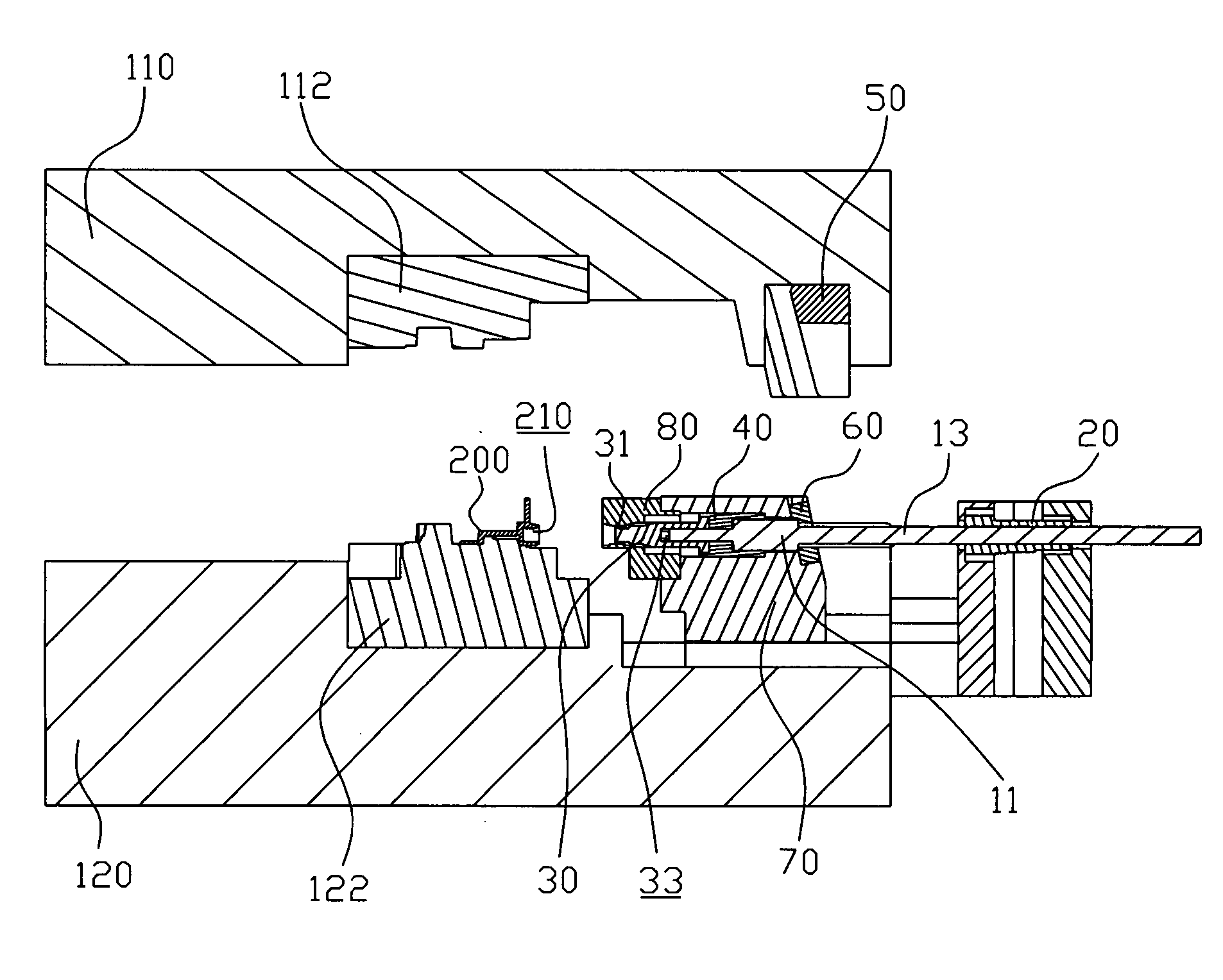
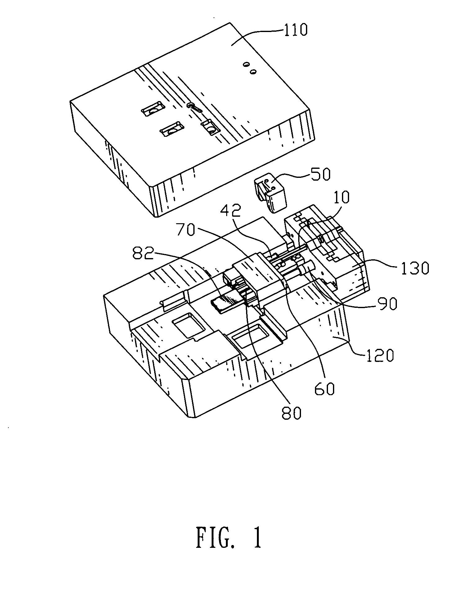
[0023] Referring to FIGS. 1, 2 and 3A, a core-pulling mechanism 1 is assembled in an injection mold. The injection mold comprises an upper mold 110 and a lower mold 120 disposed under the upper mold 110. Female mold cores 112 are disposed inside the upper mold 110, and male mold cores 122 are disposed inside the lower mold 120. The core-pulling mechanism 1 is assembled in the injection mold for pulling a slide core 80 and a threaded-pin core 30. The upper mold 110, the lower mold 120, the threaded-pin core 20 and the slide core 80 are closed together to define a mold cavity. Molten plastic materials are injected into the mold cavity to mold the plastic article 200. While the upper and lower molds 110, 120 are opened, the plastic article 200 is ejected from the mold cavity so as to be taken out.

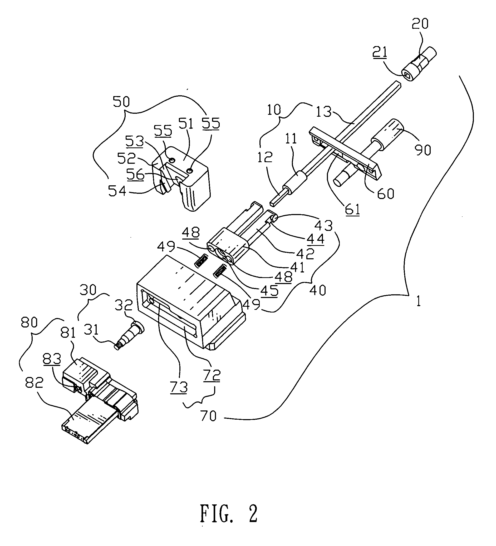
[0024] Referring to FIGS. 2 and 3A, the slide core 80 comprises an inlay block 81 and a rectangular insert body 82 extending forward from a portion of the inlay block 81. The insert body 82 i...


PUM


Abstract

A core-pulling mechanism for pulling a slide core and a threaded-pin core in an injection mold includes a hinge shaft having two ends with polygonal cross-section, an shaft sleeve assembled with a rear of the hinge shaft, a baffle block having axial through opening allowing the hinge shaft to pass through and rotate therein, a slider having a through hole for receiving the baffle block and a semi-closed transmission hole defined in a rear wall, a transmission shaft assembled in the transmission hole and fixed to the slider, and a guide block. The baffle block and the guide block have inclined guiding bulges and inclined guiding grooves engaging with each other to guide the baffle block to slide. While the transmission shaft drives the slider to move backward, the hinge shaft following with the slider move backward and slide in the shaft sleeve, thus, the distance of the backward movement of the cores pulled by the core-pulling mechanism is not limited.

Description

BACKGROUND OF THE INVENTION [0001] 1. Field of the Invention [0002] The present invention relates to a core-pulling mechanism for pulling a slide core and a threaded-pin core in an injection mold, and also relates to the injection mold with the core-pulling mechanism capable of molding plastic articles with an internal threaded hole and a big cave. [0003] 2. The Related Art [0004] A conventional injection mold is convenient for manufacturing complicated plastic articles. As shown in FIG. 8, a parting surface of a plastic article 200 is designated by P, a direction of mold opening is labeled as A-A, and both the directions that the internal threaded hole 210 and the cave 220 open on to are perpendicular to the mold opening direction A-A. In order to mold the plastic article 200, a threaded-pin core and a slide core are needed to mold the internal threaded hole 210 and the cave 220 in a mold cavity of an injection mold. While mold opening, the cores should be pulled out from the mold ...

Claims


Application Information

Patent Timeline
IPC IPC(8): B29C45/40
CPCB29C45/332B29C45/262Y10S425/058
Inventor WANG, CHIANG-CHANGCHEN, CHIH-YUHUANG, JIAN-GUANGZHENG, XIAO-JUN
Owner CHENG UEI PRECISION IND CO LTD
Why Eureka
Try Eureka