
Method for production of a dental fitting body

a technology for dental prosthetic items and fittings, applied in dental prosthetics, medical science, dentistry, etc., can solve the problems of high sintering process requirements, considerable deviations in the production of dental prosthetic items, and precise process control is required, so as to avoid accidental misalignment of the shaped part on the holder, the effect of saving tim

Inactive Publication Date: 2007-07-26
SIRONA DENTAL SYSTEMS
View PDF5 Cites 15 Cited by
  • Summary
  • Abstract
  • Description
  • Claims
  • Application Information

AI Technical Summary

Benefits of technology

[0013] In this manner, the process of defining the sintering shrinkage parameters of the batch as well as the importing of the parameters prior to each machining step can be omitted. Due to the low tolerance band of ±2%, with typical restorations of ±20 mm in length there is only an excess of ca. ±400 μm in the direction of the largest dimension. Consequently, this also leads to simplified process control for the manufacture of the raw material for the blank.
[0022] According to a further development, the machining data for the finishing operation can also be obtained by scanning the shaped part after it has been imparted with the ultimate strength properties. The machining schedule is generated from the comparison of these data with the original scanned data. The machining schedule can thus be optimized to allow for criteria such as high speed, high precision, or low wear on the tools. Scanning can be achieved by means of a scanning device on the machining unit or outside the machining unit.
[0024] According to an advantageous development, scanning of the shaped part imparted with the ultimate strength properties is undertaken only in certain regions that require a high degree of precision. Finally, a comparison of these scanning data with the coarse machining data is used to generate the machining schedule for the finishing operation, allowance being made for the shrinkage parameter acquired from the comparison. The advantage in the acquisition of the shrinkage parameter is that shorter scanning times are made possible.
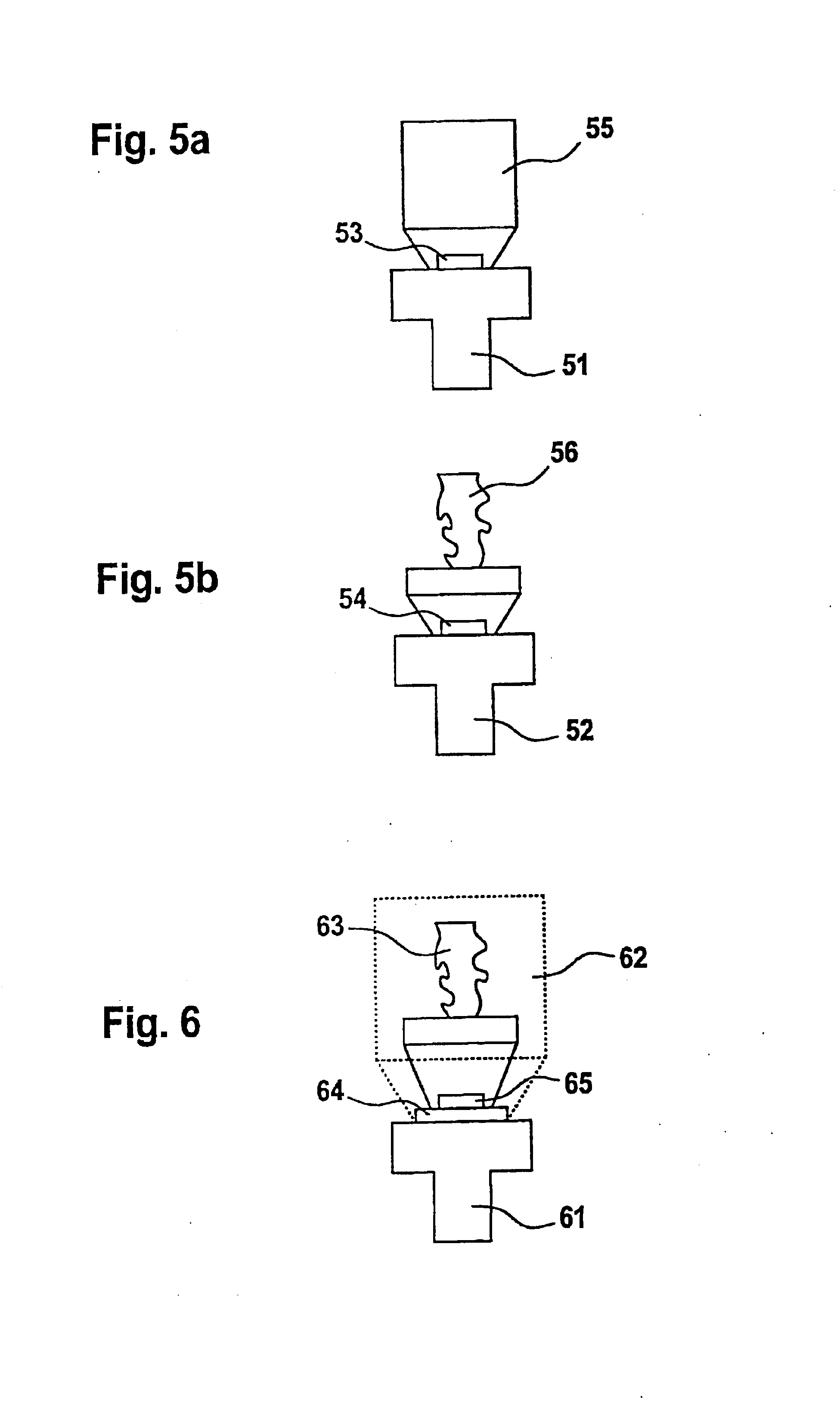
[0029] An advantageous development of the method includes scanning of the shaped part imparted with the ultimate strength properties by means of a scanning device on the machining unit. On the one hand this saves time, as the shaped part does not have to be mounted in some other device and on the other hand it contributes to the precision of the operation in that accidental misalignment of the shaped part on the holder is avoided.

Problems solved by technology

The disadvantages of this method are that exact process control is required for the manufacture of the blank, a process step is required to determine the shrinkage parameters, and high demands are placed on the sintering process.
Systems available on the market show that the sum of all of the errors arising from the process steps can lead to considerable deviations in the dental prosthetic items produced, which prosthetic items are generally in the form of a framework.

Method used


Image

  • Method for production of a dental fitting body
  • Method for production of a dental fitting body
  • Method for production of a dental fitting body

Examples


Embodiment Construction

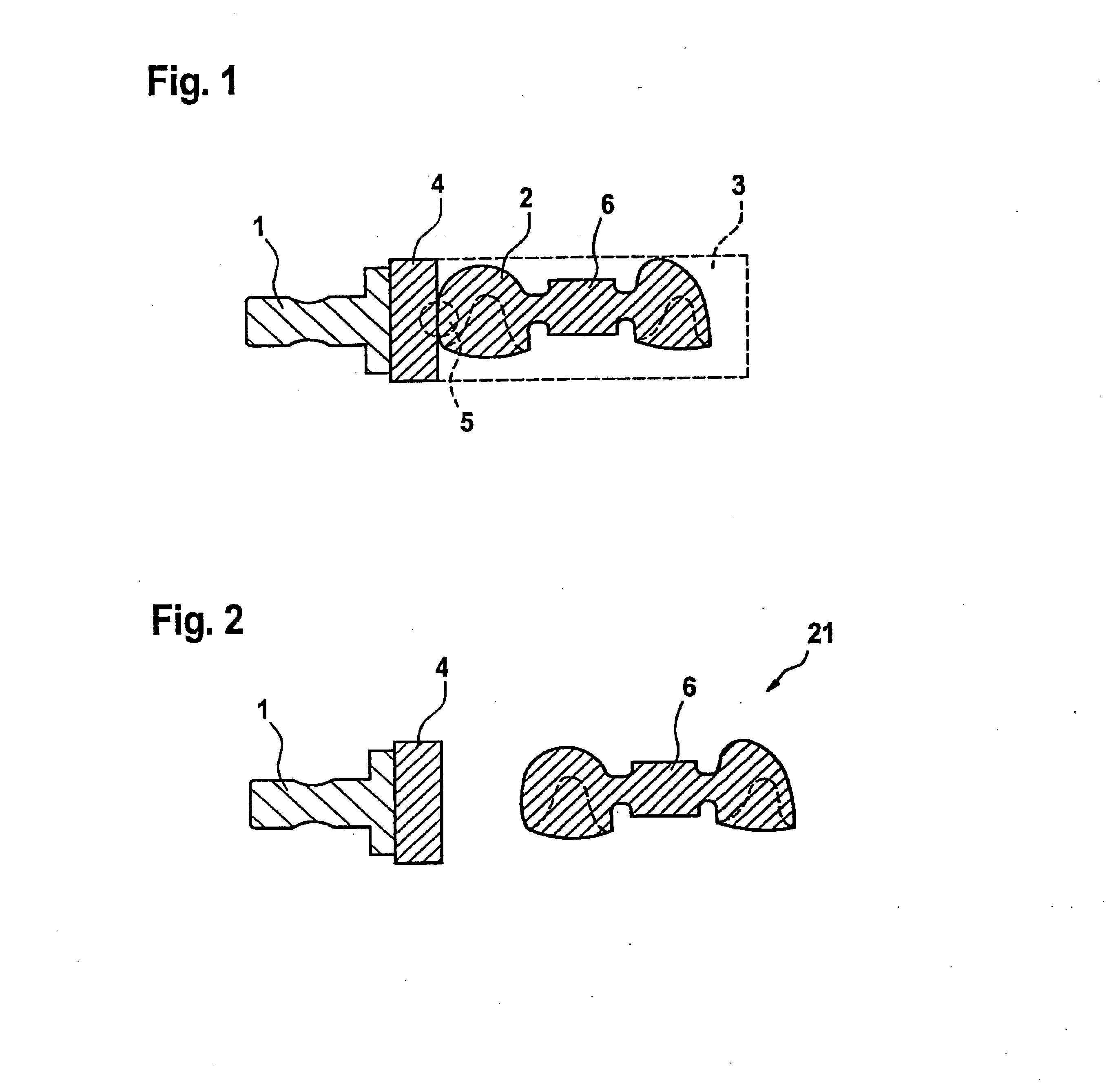
[0044] A shaped part 2 attached to a holder 1 is shown in FIG. 1. The shape of the shaped part 2 has been obtained in the actual exemplary embodiment in the course of a coarse grinding operation from a blank 3 represented by the dashed line by machining, for example, grinding or milling, and in its outer shape it already substantially corresponds to the dental prosthetic item to be manufactured. An unmachined residual region 4 of the shaped part is present in the transition region between the shaped part 2 and the holder 1. There is still a physical connection afforded by the connecting region 5 between the residual region and the shaped part 2.

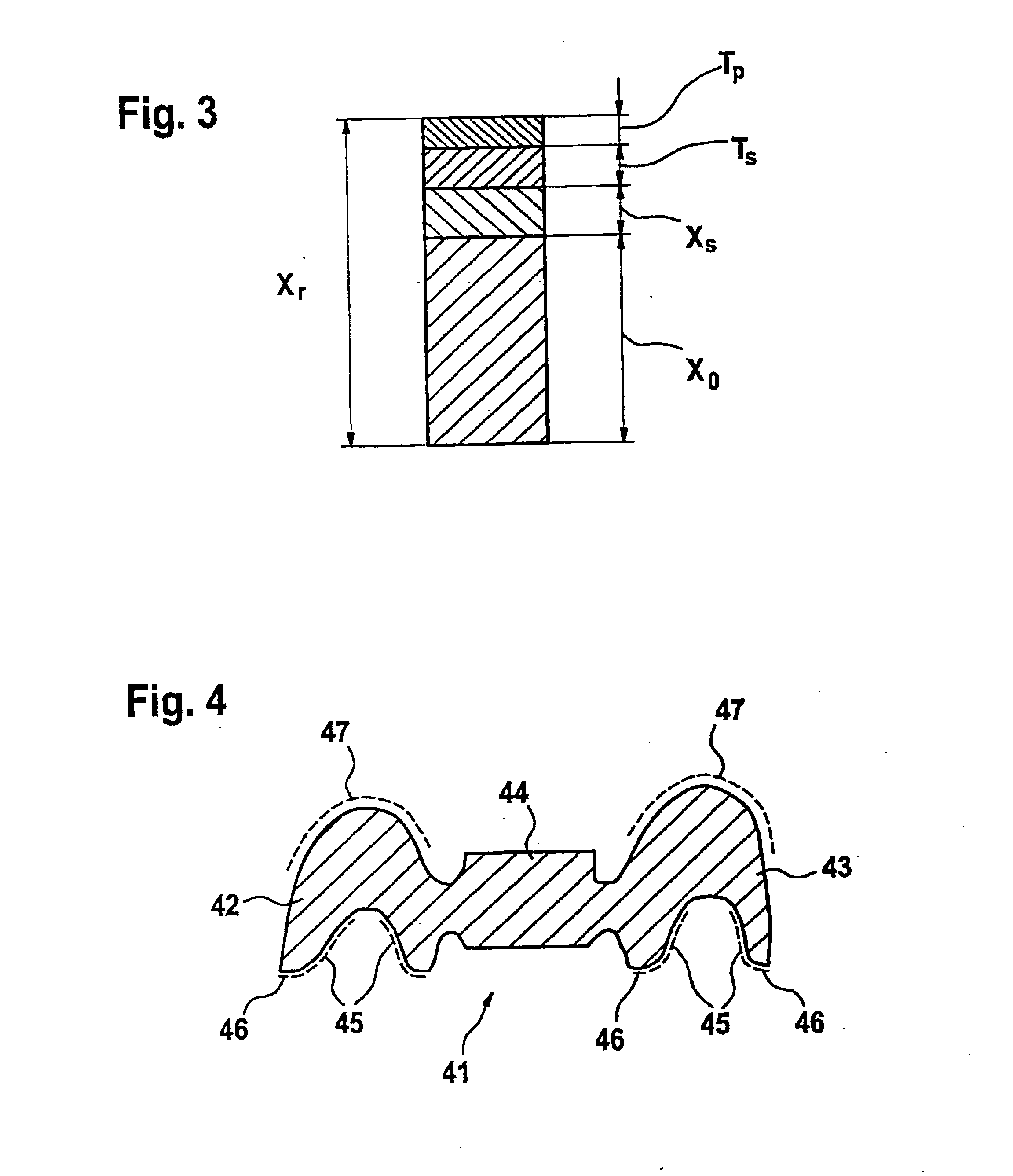
[0045] Furthermore, a reference block 6 is provided on the shaped part shown, said reference block serving for the exact measurement of the shaped part prior to and after the compacting operation in order to determine the shrinkage parameter Xs in all directions in space.

[0046] Parts of the structure represented in FIG. 1 (shaped part with ...


PUM


Abstract

The invention relates to a method for the production of a tooth prosthetic piece (21), in particular, a skeleton, using a blank (3) for machining in a material ablating 3D-forming process, said blank being made from a material not yet having the final hardness, comprising a terminal hardening of the formed piece (2) produced during the forming process to give a formed piece (2′), with the final hardness, whereby the 3D forming process is divided into coarse machining process for the blank (3) and a precise finishing process for the formed piece (2′) with the final hardness, in order to give the final form of the tooth prosthesis piece (21). The invention further relates to a mount or mounting set for carrying out the method in said particular fashion, comprising connectors for mounting the blank and suited to the shrinkage factor of the fixed formed piece. A further aspect of the invention concerns a formed piece, which, in addition to the usual over-dimension, has a further over-dimension including the tolerance range for the material shrinkage and the machining process.

Description

TECHNICAL FIELD [0001] The invention relates to a method for the fabrication of a dental prosthetic item, for example, frame structures such as dental copings or bridges, on the basis of high strength, brittle materials, especially ceramic materials such as zirconium oxide and aluminum oxide or sintered metals. [0002] Such materials are not imparted with their ultimate strength properties until a second process step is carried out, for example a sintering process, in the case of ceramic material. DESCRIPTION OF THE RELATED ART [0003] In the methods disclosed in the prior art, restorations are produced by process steps carried out as follows. [0004] First of all the blank is manufactured. To this end, the raw materials for a batch are produced, and then the mill blank is manufactured by compressing the raw material. Finally, the sintering shrinkage parameters of typically 25% for the batch are defined. Sintering shrinkage parameters vary from batch to batch typically within a toleran...

Claims


Application Information

Patent Timeline
Patent Type & Authority Applications(United States)
IPC IPC(8): A61C3/00A61C13/00
CPCA61C13/0022A61C13/0004
Inventor FORNOFF, PETER
Owner SIRONA DENTAL SYSTEMS
Learn More