Rolling boot assembly

a technology of rolling boot and assembly, which is applied in the direction of shafts, bearings, yielding couplings, etc., can solve the problems of leakage or other contamination of the joint, internal joint compromise, etc., to minimize the sensitivity to increased internal joint pressure, minimize bulging, kinking or binding of the boot, and alleviate any concerns about crimp seal connection

Inactive Publication Date: 2007-07-26
GKN DRIVELINE NORTH AMERICA
View PDF8 Cites 32 Cited by
  • Summary
  • Abstract
  • Description
  • Claims
  • Application Information

AI Technical Summary

Benefits of technology

[0005] Accordingly, the present invention provides a roll boot assembly. The roll boot assembly minimizes sensitivity to increased internal joint pressure, thereby minimizing bulging, kinking or binding of the boot when in operation. In addition, the end portion of the boot is directly secured to the constant velocity joint by the cover thereby alleviating any crimp seal connection concerns.

Problems solved by technology

The crimped connection may lead to leaks or other contamination of the joint due to a defective crimped seal between the first end of the boot and the cover.
Moreover, the internal joint may be compromised should the cover become defective or the cover connection become compromised where it attaches to the outer joint part.
In operation, the J-boot is sensitive to increased internal joint pressures, which may lead to bulging, kinking or binding of the boot.

Method used


Image

  • Rolling boot assembly
  • Rolling boot assembly
  • Rolling boot assembly

Examples


first embodiment

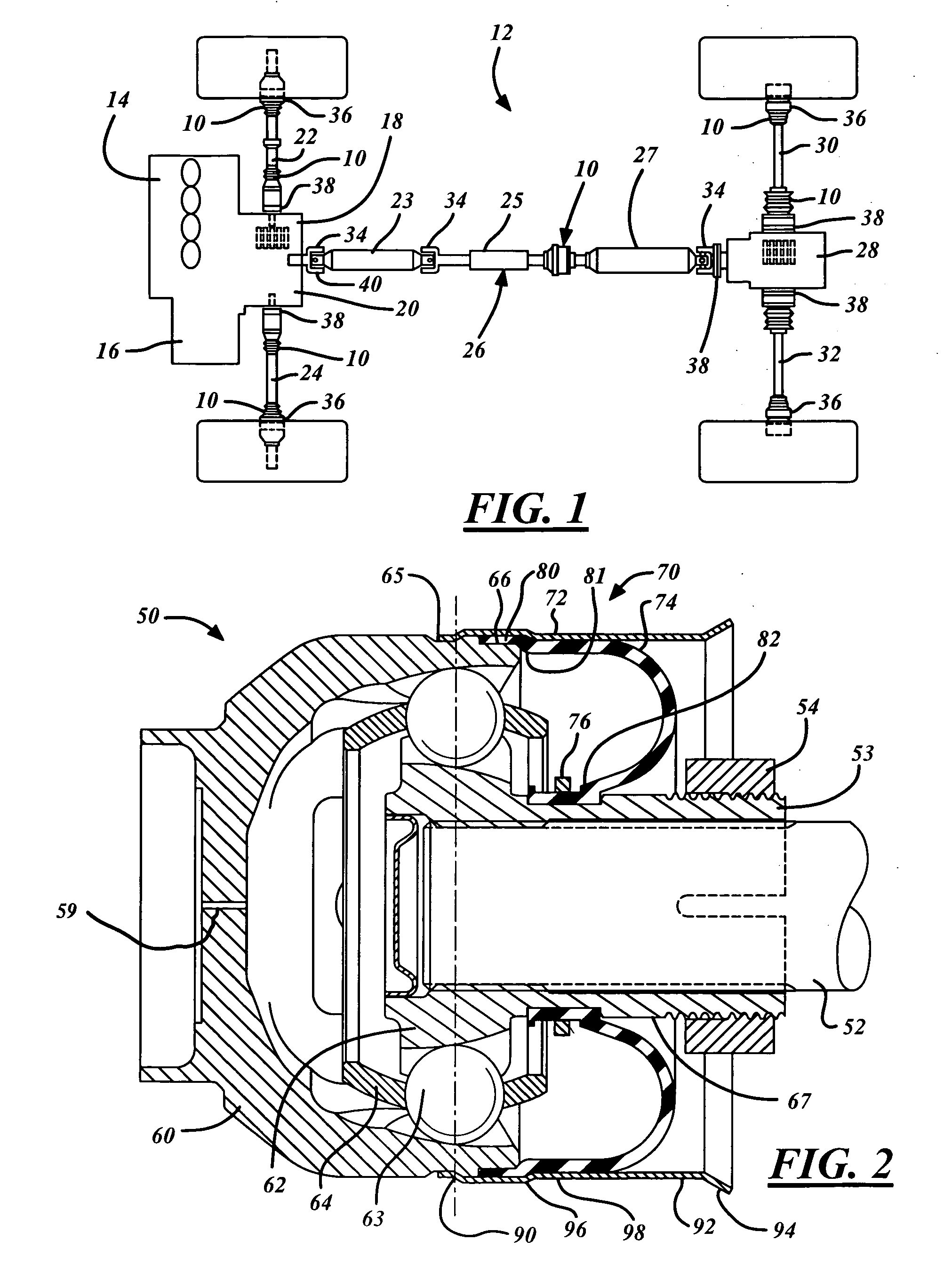
[0029]FIG. 2 shows an inventive boot assembly 70 being used to advantage with a first constant velocity joint 50. The boot assembly 70 includes a boot cover or shroud 72 and a reversed internal radius diaphragm or rolling radial boot 74 that advantageously rolls outwardly from an attached CVJ 50. The boot assembly 70 is connected to a CVJ 50 for providing a protective barrier for the internal parts and lubrication retention therein.

[0030] The boot 74 includes a compression or first section 80 at one end and an attachment or second section 82 at the other end. The first section 80 of the boot 74 is connected directly to the outer joint part 60 and further retained thereto by the shroud 72. Optionally, the first section 80 of the boot 74 is attached to the shroud 72, thereby being connectable, directly or indirectly, to the outer joint part 60. The second section 82 of the boot 74 is connected to an attachment surface 67 of an inner joint part 62 by resilient retention of the boot mat...

second embodiment

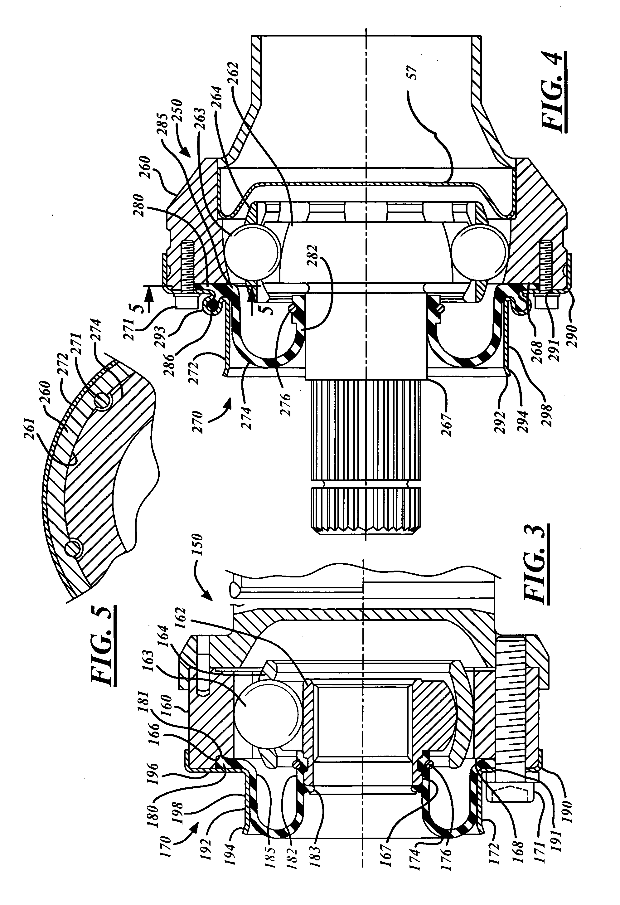
[0035]FIG. 3 shows an inventive boot assembly 170 being used to advantage with a second constant velocity joint 150. The boot assembly 170 includes a boot cover or shroud 172 and a reversed internal radius diaphragm or rolling radial boot 174 that advantageously rolls outwardly from an attached CVJ 150. The boot assembly 170 is connected to a CVJ 150 for providing a protective barrier for the internal parts and lubrication retention therein.

[0036] The boot 174 includes a compression or first section 180 at one end and an attachment or second section 182 at the other end. The first section 180 of the boot 174 extends radially outward at a conforming portion 185 in that the first section 180 of the boot 174 is compressively retained directly to a front face 168 of the outer joint part 160 by the shroud 172. Optionally, the boot 174 may be compressively retained in a recess or groove 166 located on the CVJ 150. The second section 182 of the boot 174 is connected to an attachment surfac...

third embodiment

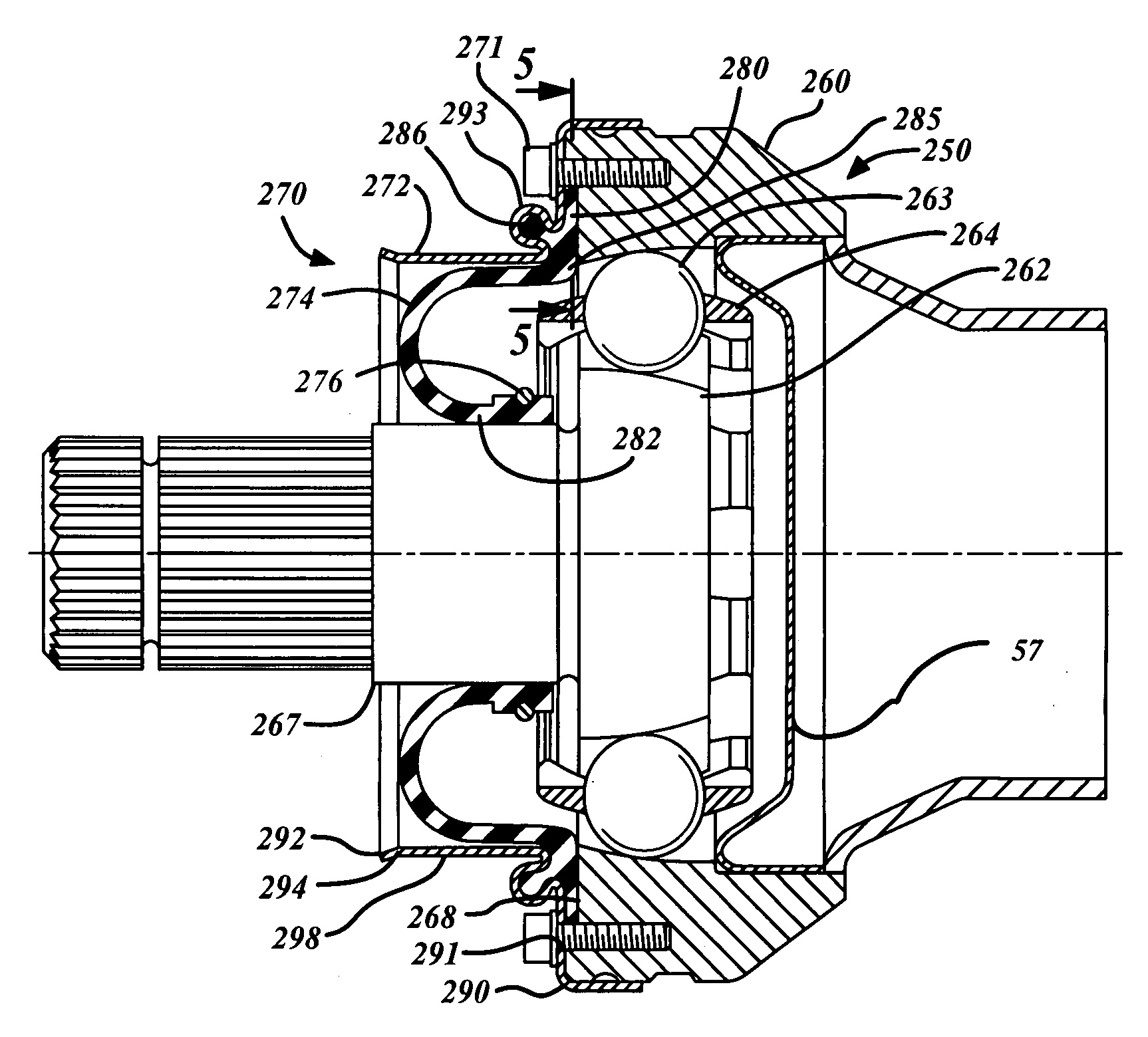
[0039]FIG. 4 shows an inventive boot assembly 270 being used to advantage with a third constant velocity joint 250. The boot assembly 270 includes a boot cover or shroud 272 and an external radius diaphragm or rolling radial boot 274 that advantageously rolls outwardly from an attached CVJ 250. The boot assembly 270 is connected to a CVJ 250 for providing a protective barrier for the internal parts and lubrication retention therein.

[0040] The boot 274 includes a compression or first section 280 at one end and an attachment or second section 282 at the other end. The first section 280 of the boot 274 extends radially outward at a conforming portion 285, allowing the first section 280 of the boot 274 to be compressively retained directly to a front face 268 of the outer joint part by the shroud 272. The second section 282 of the boot 274 is connected to an attachment surface 267 of an inner joint part 262 by resilient retention of the boot material, or by an optional retaining ring or...


PUM


Abstract

A rolling boot assembly includes a shroud having a first portion and a second portion, and a radial boot having a first section and a second section. The second portion of the shroud has a free end. The first section of the radial boot is connected to the first portion of the shroud advantageously allowing the radial boot to roll axially toward the second portion of the shroud when the second section of the radial boot is selectively attached to a shaft or an inner joint part and the first portion of the shroud is selectively connected to an outer joint part. The second portion of the shroud remains unconnected. Also provided is a constant velocity joint assembly.

Description

TECHNICAL FIELD [0001] The present invention relates generally to a rolling boot assembly for motor vehicle shaft joints, and more particularly concerns a reversed internal rolling radial boot assembly. BACKGROUND [0002] Constant velocity joints connecting shafts to drive units are common components in automotive vehicles. The drive unit typically has an output shaft or an input shaft for receiving the joint. Typically, the drive unit is an axle, transfer case, transmission, power take-off unit or other torque device, all of which are common components in automotive vehicles. Typically, one or more joints are assembled to the shaft to form a propeller or drive shaft assembly. It is the propeller shaft assembly, which is connected, for instance, at one end to an output shaft of a transmission and, at the other end, to an input shaft of a differential. The shaft is solid or tubular with ends adapted to attach the shaft to an inner race of the joint thereby allowing an outer race conne...

Claims


Application Information

Patent Timeline
Patent Type & Authority Applications(United States)
IPC IPC(8): F16C3/00
CPCF16J3/042F16D3/845F16D3/223F16D3/227
Inventor WORMSBAECHER, HANSLAMOTHE, ERIC
Owner GKN DRIVELINE NORTH AMERICA
Why Eureka
Try Eureka