Object discretization to particles for computer simulation and analysis

Active Publication Date: 2007-07-26
PERATON INC
View PDF10 Cites 7 Cited by
  • Summary
  • Abstract
  • Description
  • Claims
  • Application Information

AI Technical Summary

Benefits of technology

[0005] In addition, a technique is provided for determining the orientation of particles representing each of two or more objects involved in an interaction a

Problems solved by technology

However, there is a tradeoff between accuracy and simulation run time.
Generally, the more complex a simulation is in order to achieve better accuracy, the longer it takes for that simulation to run to completion.
In fact, very complex computer simulations, such as

Method used


Image

  • Object discretization to particles for computer simulation and analysis
  • Object discretization to particles for computer simulation and analysis
  • Object discretization to particles for computer simulation and analysis

Examples


Embodiment Construction

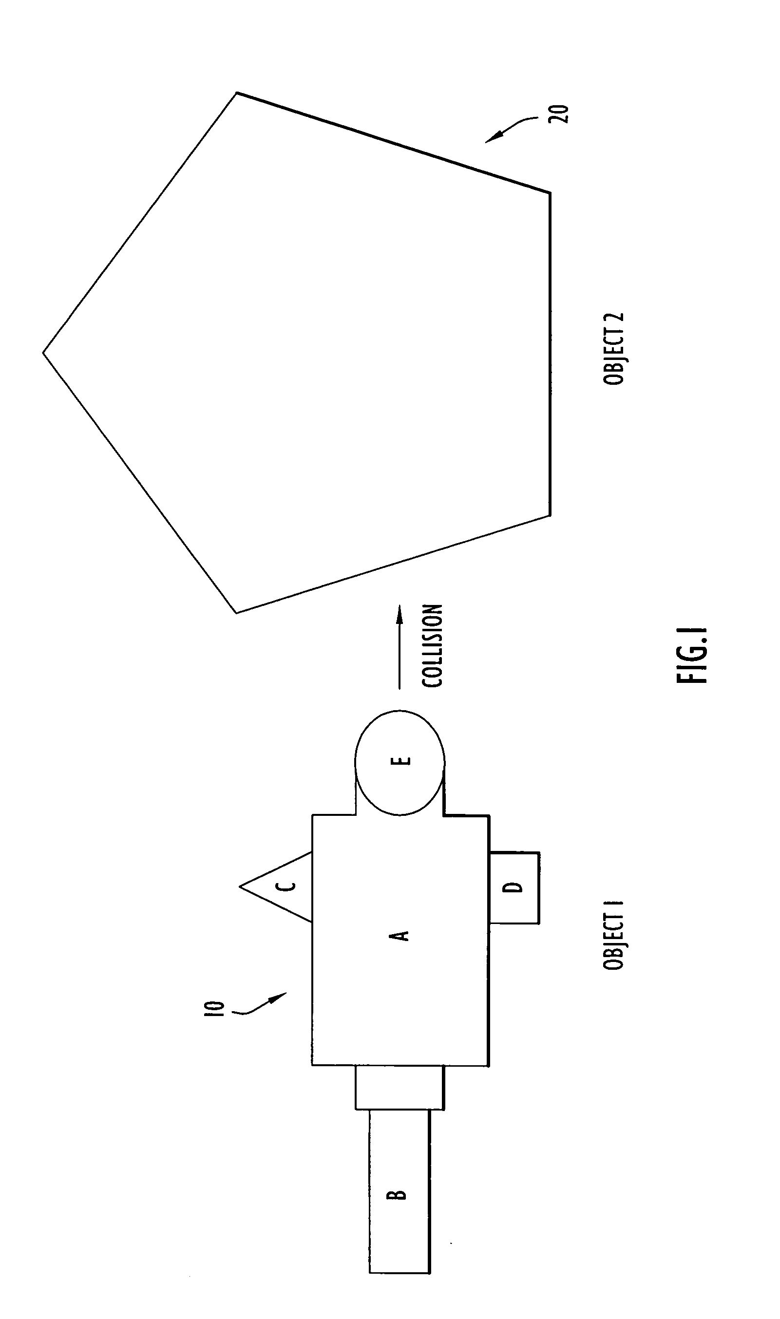
[0012] Referring first to FIG. 1, an experiment is depicted in which a first object 10 is to collide with a second object 20. The objects 10 and 20 could be any two objects that may collide with each other, or one of which may explode or detonate near or on the other, etc. Either or both objects may be moving, or one object may be exploding in or near another object. Non-limiting examples of the experiment include: object 20 is stationary (e.g., a building structure) and object 10 is moving and collides or explodes near object 20, where object 10 is a moving vehicle such as a land vehicle, air vehicle (airplane, missile, etc.); object 20 is moving and object 10 is moving and the two objects collide with each other, one of which may or may not set off an explosion upon or near impact, where object 20 is an air vehicle and object 10 is an air vehicle; objects 10 and 20 are both stationary and one explodes inside or near the other object. It should be understood that while only two obj...


PUM


Abstract

A computer-implemented method is provided for generating data representing an object involved in a computer-implemented simulation of a physical experiment. Data describing geometric dimensions and material for the object is received as input. The data may be broken down into data representing distinct components of the object. Data is generated that describes a base parent volume region that extends at least beyond extents of the geometric dimensions of a portion of the object. Next, data is generated that describes child volume regions produced by subdividing the base parent volume region into the child volume regions each having dimensions that are a fraction of the dimensions of the base parent volume region. The data describing each child volume region is examined to determine whether vertices of each of the child volume regions are in the interior or exterior of the portion. The subdivision and examining process is repeated for each child volume region that is not entirely in the interior or entirely in the exterior of the portion to further subdivide each such child volume region to produce data describing a set of child volume regions that do not satisfy the criteria for further subdivision. Data is generated that uniformly distributes particles at positions of the portion of the object based on dimensions of the child volume region in the set, wherein the data for each particle describes a mass density, velocity, pressure, stress and energy at a position and a collection of the particles represent the object portion for use in the computer-implemented simulation.

Description

FIELD OF THE INVENTION [0001] The present invention relates to computer simulations of physical phenomena, and more particularly to reducing the amount of data representing objects involved in such computer simulations. BACKGROUND OF THE INVENTION [0002] Computer simulations for experiments involving the impact of one object with another object have widespread applications. For example, automobile manufacturers use such simulations in designing safer vehicles. In a totally different technology field, scientist uses such simulations to study the effectiveness of a missile destroying a moving or stationary target. Regardless of the particular application, it is an overall goal to design a computer simulation that can accurately produce data concerning possible outcomes of the physical phenomena of interest pertaining to two or more objects. However, there is a tradeoff between accuracy and simulation run time. Generally, the more complex a simulation is in order to achieve better accu...

Claims


Application Information

Patent Timeline
IPC IPC(8): G06F17/10
CPCG06F17/5009G06T2210/56G06T17/005G06F2217/16G06F2111/10G06F30/20
Inventor TILLMAN, STEVENWITZIG, ANDREW
Owner PERATON INC
Why Eureka
Try Eureka