Hybrid disk drive and method of controlling data therein

a hybrid disk drive and data controller technology, applied in the field of hybrid disk drives, can solve the problems of compromising the data speed of an hdd, affecting the efficiency of data flow, so as to reduce power consumption, efficiently control data flow, and optimize data speed

Active Publication Date: 2007-07-26
SAMSUNG ELECTRONICS CO LTD
View PDF5 Cites 26 Cited by
  • Summary
  • Abstract
  • Description
  • Claims
  • Application Information

AI Technical Summary

Benefits of technology

[0007]The present invention provides a hybrid disk drive for achieving speed optimization and minimization of power consumption by installing a flash memory device in the hybrid disk drive and efficiently controlling data flow between the flash memory device and the hybrid disk drive. A hybrid disk drive includes a volatile memory unit, a nonvolatile memory unit, a disk unit, a host interface and a buffer controller disposed between the volatile memory unit, the nonvolatile memory unit, the host interface and the disk unit. The disk unit stores data by magnetizing the surface of the disk. The host interface receives a read data command from the host and transmits the data stored in the volatile memory unit to the host. The buffer controller is configured to read the data from the nonvolatile memory unit if the data is not stored in the volatile memory unit when the read data command is received from the host interface. The buffer controller also controls the storing of the read data in the volatile memory unit if the data is stored in the nonvolatile memory unit. Alternatively, if the data is not stored in the nonvolatile memory unit, the controller reads the data from the disk unit and stories it in the volatile memory unit.

Problems solved by technology

However, HDD devices do not have a device or method used to control the efficient transfer of data from and to such flash memory devices.
The absence of such a device or method compromises data speed of an HDD as well as necessary poser consumption.

Method used


Image

  • Hybrid disk drive and method of controlling data therein
  • Hybrid disk drive and method of controlling data therein
  • Hybrid disk drive and method of controlling data therein

Examples


Embodiment Construction

[0016]The present invention will now be described more fully hereinafter with reference to the accompanying drawings, in which preferred embodiments of the invention are shown. This invention, however, may be embodied in many different forms and should not be construed as limited to the embodiments set forth herein. Rather, these embodiments are provided so that this disclosure will be thorough and complete, and will fully convey the scope of the invention to those skilled in the art. In the drawings, like numbers refer to like elements throughout.

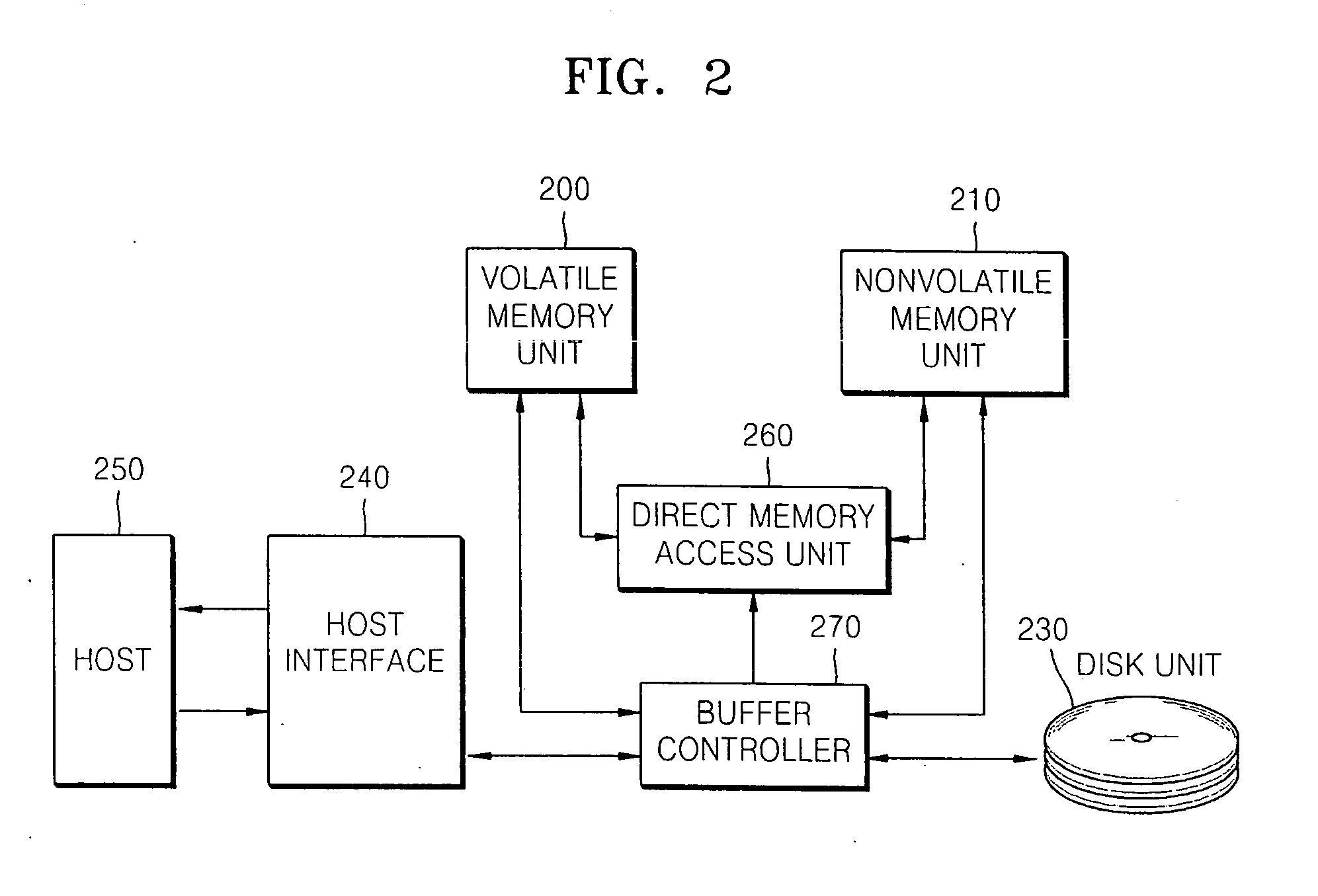
[0017]FIG. 2 is a block diagram of a hybrid disk drive including a volatile memory unit 200, a nonvolatile memory unit 210 and a disk unit 230. Volatile memory unit 200 may include, for example, a synchronous dynamic random access memory (SDRAM) or a static dynamic random access memory (SRAM). Nonvolatile memory unit 210 may include, for example, a flash memory device. Disk unit 230 stores data by magnetizing the surface of the disk using ...


PUM


Abstract

A hybrid disk drive is utilized to achieve speed optimization and minimization of power consumption by installing a flash memory device in the hybrid disk drive and efficiently controlling data flow between the flash memory device and the disk drive. The hybrid disk drive includes a, volatile memory unit, a nonvolatile memory unit, a disk unit, a host interface and a buffer controller disposed between the volatile memory unit, the nonvolatile memory unit, the host interface and the disk unit. The disk unit stores data by magnetizing the surface of the disk. The host interface receives a read data command from the host and transmits the data stored in the volatile memory unit to the host. The buffer controller is configured to read the data from the nonvolatile memory unit if the data is not stored in the volatile memory unit when the read data command is received from the host interface. The buffer controller also controls the storing of the read data in the volatile memory unit if the data is stored in the nonvolatile memory unit. Alternatively, if the data is not stored in the nonvolatile memory unit, the controller reads the data from the disk unit and stories it in the volatile memory unit.

Description

BACKGROUND OF THE INVENTION[0001]1. Field of the Invention[0002]The present invention relates to a disk drive, and more particularly, to a hybrid disk drive and a method of controlling data stored on the hybrid disk drive.[0003]This application claims the benefit of Korean Patent Application No. 10-2006-0006802, filed on Jan. 23, 2006, in the Korean Intellectual Property Office, the entire contents of which are hereby incorporated by reference.[0004]2. Discussion of Related Art[0005]FIG. 1 is a schematic plan view of a conventional hard disk drive (HDD) 100 which includes at least one disk 120, rotated by a spindle motor 110, and a head 130 located adjacent to the surface of the disk 120. The head 130 can read or write information from or to disk 120 by sensing a magnetic field on the surface of the disk 120 or by magnetizing the surface of the disk. Although a single head 130 is shown in FIG. 1, head 130 includes a write head for magnetizing disk 120 and a separate read head for se...

Claims


Application Information

Patent Timeline
Patent Type & Authority Applications(United States)
IPC IPC(8): G06F13/00
CPCG06F3/0613G06F3/0625G06F3/0659G06F3/068Y02B60/1246G11B19/04G11B20/10Y02B60/1225G06F12/0866Y02D10/00G11B19/02
Inventor LEE, JAE-SUNG
Owner SAMSUNG ELECTRONICS CO LTD
Why Eureka
Try Eureka