Constant EGR rate engine and method

a constant egr rate, engine technology, applied in the direction of machines/engines, mechanical equipment, non-fuel substance addition to fuel, etc., can solve the problems of reducing the emissions requirements of engines, increasing the demand for egr gas flow, and lowering the fuel economy and power output of engines

Active Publication Date: 2007-08-02
INT ENGINE INTPROP CO LLC
View PDF15 Cites 104 Cited by
  • Summary
  • Abstract
  • Description
  • Claims
  • Application Information

AI Technical Summary

Problems solved by technology

Nevertheless, even under conditions of low Delta P, demands for EGR gas flow increase as emissions requirements for the engine decrease.
One disadvantage of this method is that pumping loss in the engine increases thus lowering fuel economy and the power output of the engine.

Method used


Image

  • Constant EGR rate engine and method
  • Constant EGR rate engine and method
  • Constant EGR rate engine and method

Examples


Embodiment Construction

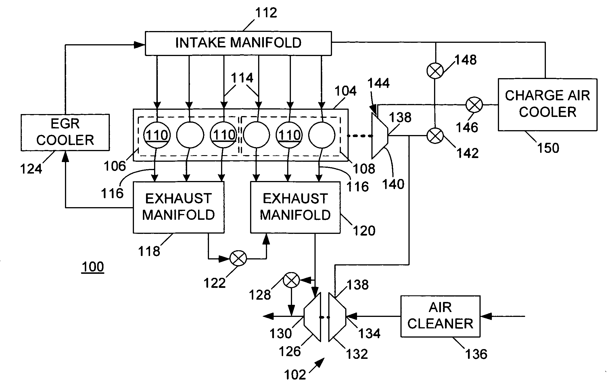
[0014] The following describes an apparatus for and method of operating an internal combustion engine under substantially constant rates of EGR. An EGR rate may be defined as a percentage of fluid input to the engine by mass. Air, or a mixture of air and recirculated exhaust gas, may be ingested by an engine during operation. The portion, or percentage, of recirculated exhaust gas in the mixture represents what is referred to in the art as an EGR rate. The embodiments of this invention that are disclosed below pertain to operation of an engine under a constant rate of EGR over almost an entire range of engine operation. The constant EGR rate that advantageously may be employed is not entirely determined by an opening of an EGR valve; rather, it is determined by a hardware configuration of the engine.

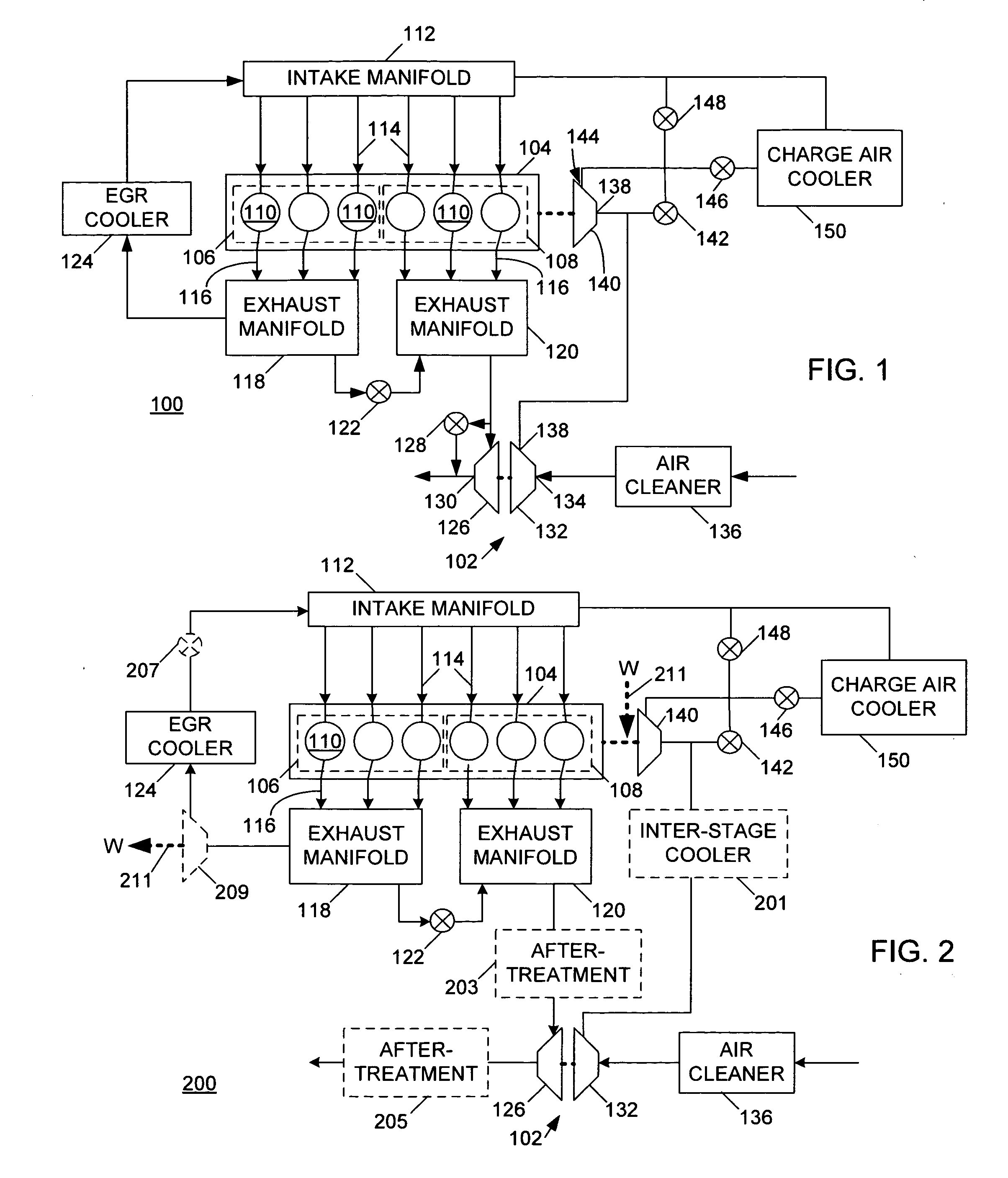
[0015] An engine 100 having a turbocharger 102 is shown in FIG. 1. The engine 100 includes a crankcase 104 having a first plurality of cylinders 106 and a second plurality of cylinders ...


PUM


Abstract

An internal combustion engine (100) includes a first exhaust manifold (120), and a second exhaust manifold (118) fluidly connected to the first exhaust manifold (120) through an exhaust valve (122). An exhaust gas recirculation (EGR) cooler (124) constantly fluidly connects the second exhaust manifold (118) with an intake manifold (112). A turbocharger (102) has a turbine (126) in fluid communication with the first exhaust manifold (120), and a compressor (132) in fluid communication with a supercharger (140). A charge air cooler (150) fluidly connects the supercharger (140) with the intake manifold (112).

Description

FIELD OF THE INVENTION [0001] This invention relates to internal combustion engines, including but not limited to engines having turbochargers and exhaust gas recirculation (EGR) systems. BACKGROUND OF THE INVENTION [0002] Exhaust gas recirculation (EGR) for internal combustion engines is known. Typical compression ignition engines may also cool recirculated exhaust gas in EGR coolers. In an engine that is not naturally aspirated, for example, an engine having a turbocharger, a difference in pressure between the exhaust system and intake system of the engine may determine a maximum amount of exhaust gas that may be recirculated from the exhaust into the intake of the engine. [0003] Exhaust gas in the exhaust system upstream of the turbocharger is at an exhaust pressure, or exhaust back pressure (EBP) during operation of the engine. Conversely, air or a mixture of air and exhaust gas in the intake manifold of the engine is at an intake manifold pressure, or a manifold absolute pressu...

Claims


Application Information

Patent Timeline
Patent Type & Authority Applications(United States)
IPC IPC(8): F02B33/44
CPCF02B29/0418F02B37/16F02B37/18F02B37/24F02M25/0711F02M25/0727F01N13/009F02M25/0749Y02T10/121Y02T10/146Y02T10/144F02B37/04F02M25/0739F02M26/08F02M26/23F02M26/34F02M26/43Y02T10/12
Inventor ROWELLS, ROBERT L.
Owner INT ENGINE INTPROP CO LLC
Why Eureka
Try Eureka