Skillet power system

a power system and skillet technology, applied in the field of skillet power systems, can solve the problems of increasing the total friction of the system, increasing the manufacturing cost of the system, and prolonging the length of the conductor, so as to reduce manufacturing, installation and maintenance costs, and facilitate the installation of the system.

Inactive Publication Date: 2007-08-02
JERVIS B WEBB INT CO
View PDF54 Cites 3 Cited by
  • Summary
  • Abstract
  • Description
  • Claims
  • Application Information

AI Technical Summary

Benefits of technology

[0013] Another aspect of the present invention is that the above system allows the length of the conductor to be limited to approximately that of about a single skillet, if each skillet includes an electrical receiving device. That is, if the length of a production area is 10 skillets, the conductor of the present invention only has to be about the length of one skillet or slightly greater, because contact between the conductor and any electrical receiving device will transfer the power to that skillet and any connected adjacent skillets. The actual required distance of the conductor is the length that would ensure that the conductor maintains continuous contact with at least one collector shoe on one skillet along the train of skillets at any given time. The conductor may also be located at any point along the production area and is not limited to a certain spot, such as the beginning of the production area, thereby making installation of the system easier along with lower installation costs. Instead of minimizing the conductor to approximately the length of a single skillet, the conductor may, for example, extend approximately the length of two skillets, thereby allowing every other skillet to include a collector or electrical receiving device. In some installations, a combination of a reduced conductor and limiting the number of skillets with collectors will provide the lowest manufacturing, installation, and maintenance costs.
[0014] Reducing the length of the conductor also reduces the friction wear that occurs between the electrical receiving devices or collector shoes and conductor and therefore reduces wea

Problems solved by technology

One drawback common to these systems is increased manufacturing costs due to excessive conductor lengths.
The extended length of the conductor also increases the total friction of the system, as each collector shoe stays engaged on the conductor throughout the production area, requiring

Method used


Image

  • Skillet power system
  • Skillet power system
  • Skillet power system

Examples


Embodiment Construction

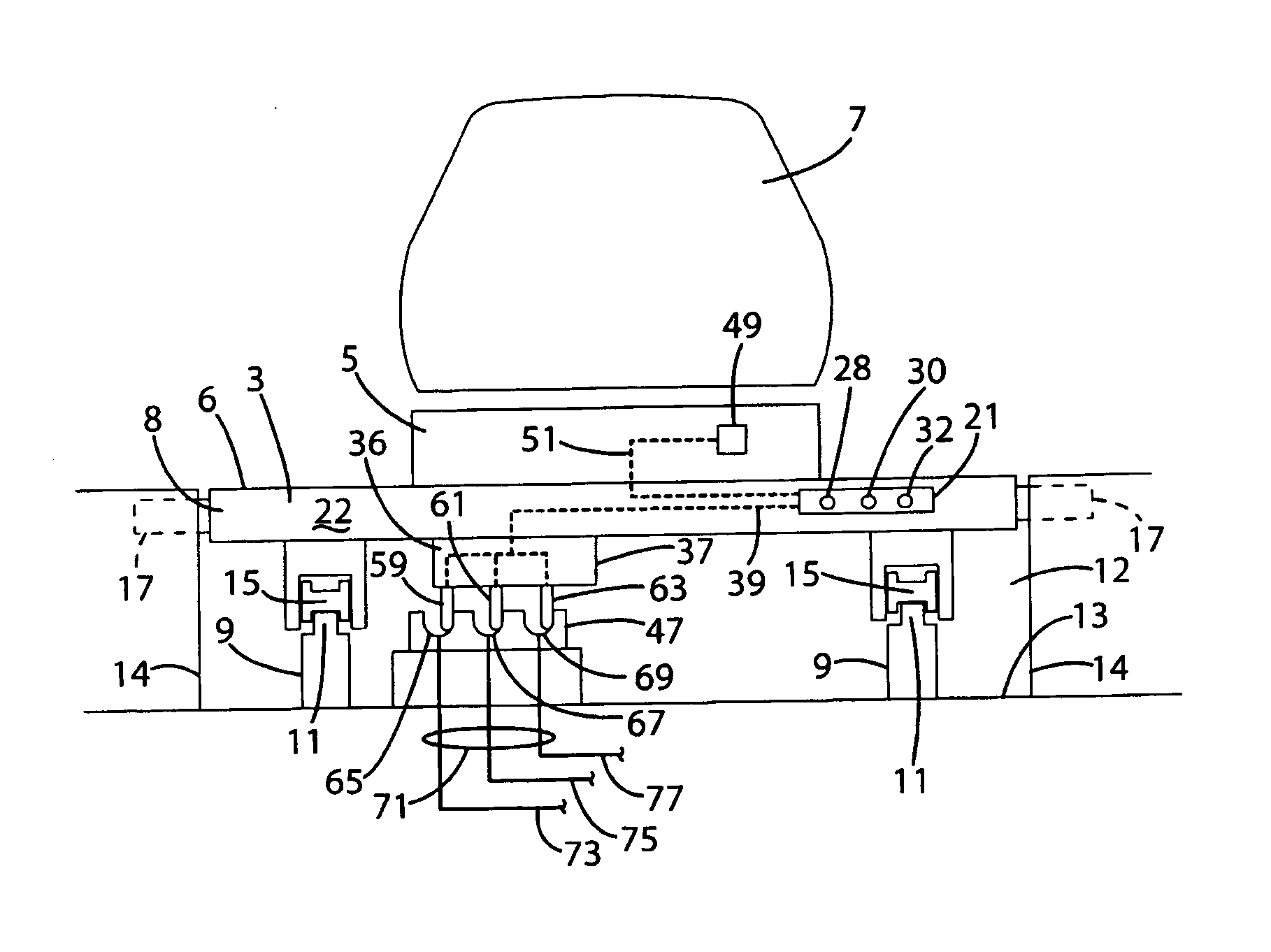
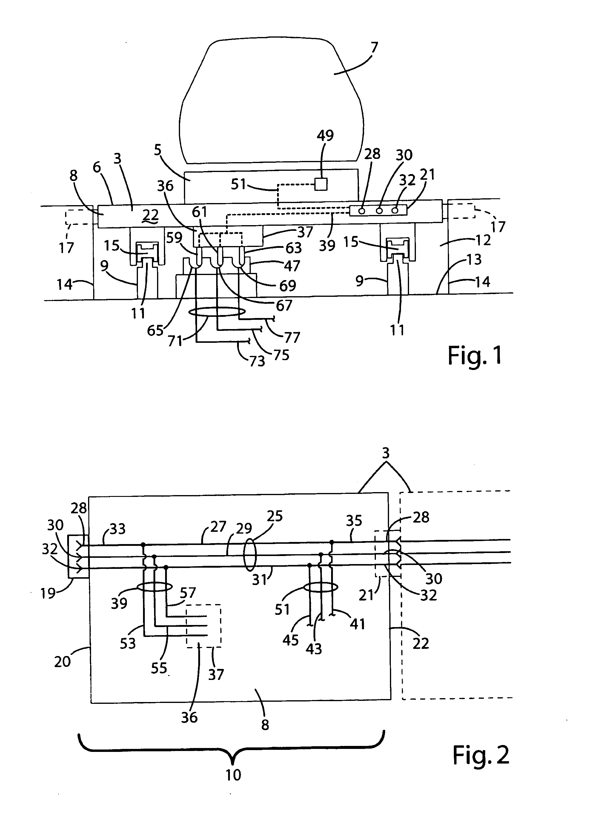
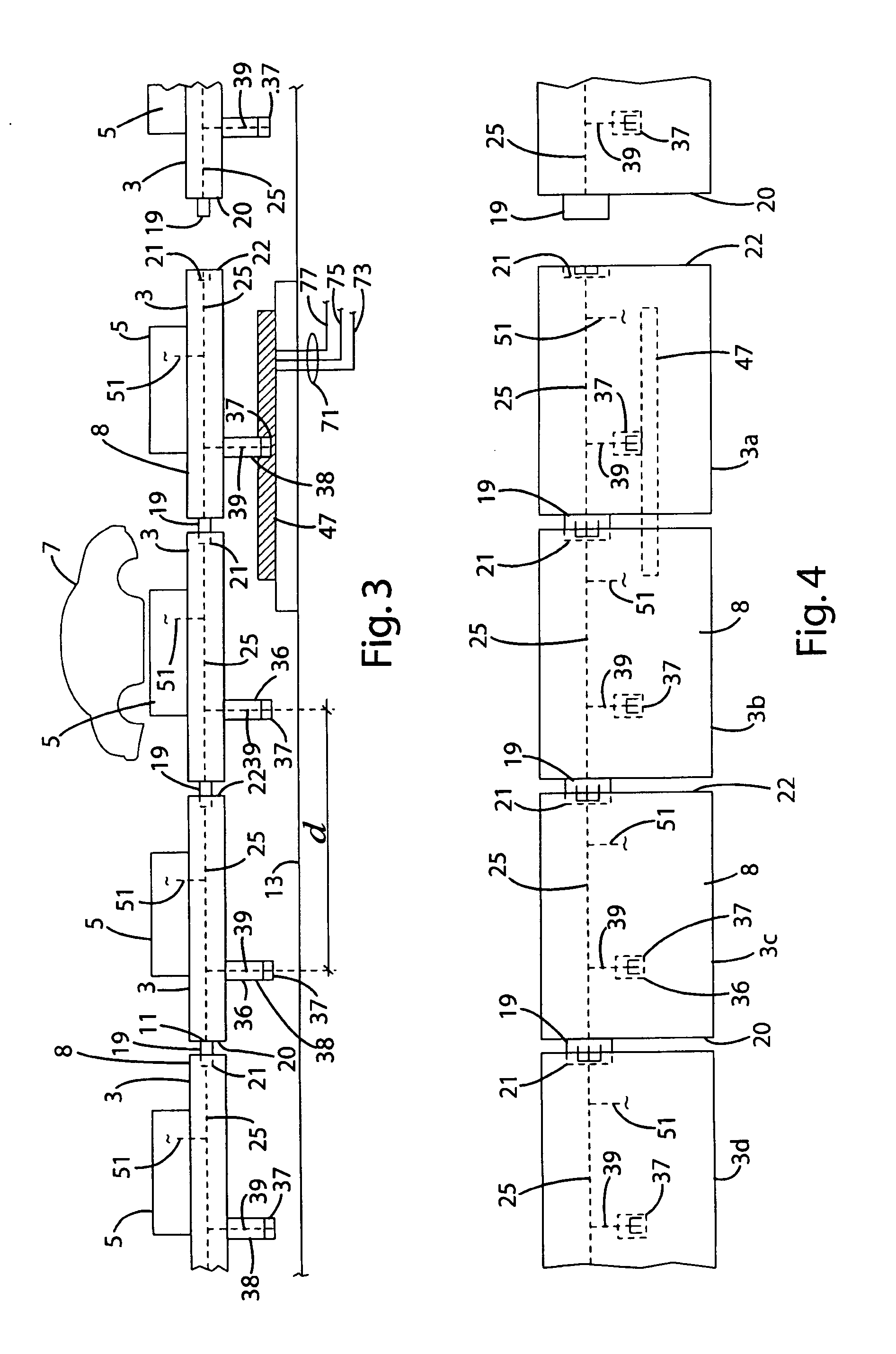
[0022] The present invention is directed to a skillet 3 for supporting a workpiece 7, as illustrated in FIG. 1. The skillet 3 generally includes a platform 8 having an upper surface 6 and an upper support 5 extending from the platform 8 and adapted to support thereon a workpiece 7. The workpiece 7 is illustrated in the drawings as an automobile body; however, it could be any other item needing assembly. Each skillet 3 includes an electrical assembly 10, as illustrated in FIG. 2, having at least one contact 29 for engaging a contact on an adjacent skillet to allow the passage of electrical power, and if desired, data signals between adjacent skillets. While the present invention is described below in detail for the passage of electricity, the present invention may transmit data signals instead.

[0023] The conveyor assembly 2 may have a variety of configurations, depending on the type of workpiece, production tasks to be performed, the facility, and a variety of other considerations. ...


PUM


Abstract

The invention relates to conveyor systems with skillets adapted with connectors to enable power to be conveyed between skillets that are abutted together along a production area. With the skillets being electrically connected, the conductor only needs to supply power the electrical receiving device of a single skillet at any given time. The conductor in turn can be limited to a length of about one skillet, which reduces the wear, as well as installation, repair and maintenance costs.

Description

FIELD OF THE INVENTION [0001] The present invention is directed to a conveyor system having a plurality of skillets adapted to be abutted together to form a moving platform upon which production tasks can be performed, and in particular to a conveyor system where electrical power or data signals can be provided between each skillet, and between each skillet and a controller or power source. BACKGROUND OF THE INVENTION [0002] Manufacturing facilities, such as automobile assembly plants, use moving skillets to convey large parts throughout the facility. The skillets are commonly larger than the workpiece to provide a platform for a worker to perform production tasks while the skillet is in motion. In other words, the skillet may form a moving floor, allowing the worker to perform a production task while moving with the skillet and workpiece. When the production task is complete, the worker may leave the skillet by walking to an adjoining skillet or stepping from the skillet to the flo...

Claims


Application Information

Patent Timeline
IPC IPC(8): B65G37/00
CPCB62D65/18H02J13/00H02J4/00B65G54/02B65G47/04B62D65/00B65G54/00
Inventor ELLENS, DAN
Owner JERVIS B WEBB INT CO
Why Eureka
Try Eureka