Sensor with trigger pixels for imaging of pulsed radiation

a radiation sensor and sensor technology, applied in the field of triggering radiation sensors, can solve the problems of increasing cost and reducing yield, increasing complexity, and esd/emc susceptibility of prior art devices giving false triggers, and achieving the effect of rapid response to detection

Inactive Publication Date: 2007-08-02
E2V TECH (UK) LTD
View PDF15 Cites 68 Cited by
  • Summary
  • Abstract
  • Description
  • Claims
  • Application Information

AI Technical Summary

Problems solved by technology

This additional complexity increases cost and reduces yield.
The ESD / EMC susceptibility of the prior art devices also gives false triggers.
If image photosites are also used for triggering they cannot be separately optimised for both imaging and triggering.
Schemes which use a sparse array of image pixels for triggering require more complex address circuits or operational modes and risk introduction of fixed pattern noise in the image as a result of some pixels having been treated differently from others.

Method used


Image

  • Sensor with trigger pixels for imaging of pulsed radiation
  • Sensor with trigger pixels for imaging of pulsed radiation
  • Sensor with trigger pixels for imaging of pulsed radiation

Examples


Embodiment Construction

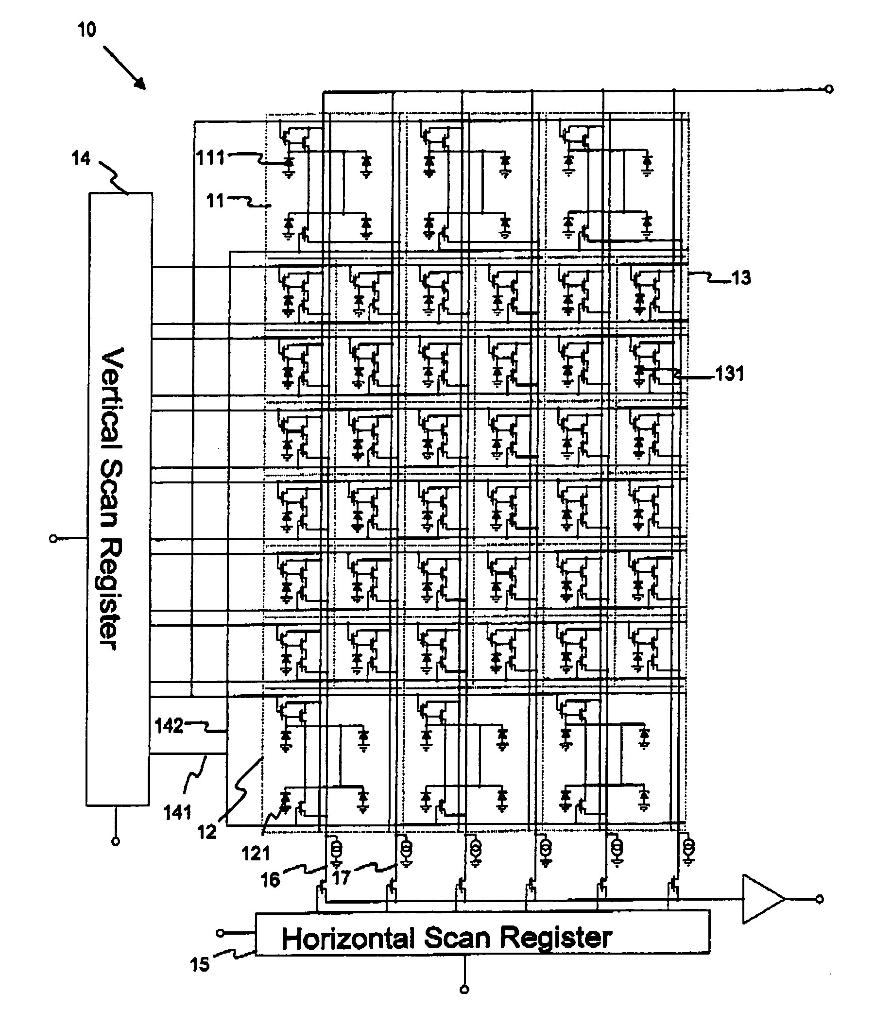
[0051] Referring to FIG. 1, a CMOS image array 10 according to the invention has a plurality of rows of image pixels 13, read by a vertical scan register 14 and a horizontal scan register 15 in a known manner. In addition there are provided a top row of trigger pixels 11 and a bottom row of trigger pixels 12. The trigger pixels 11, 12 each occupy four times an area of each of the image pixels and have four photodiodes 111, 121 connected in parallel compared with a single photodiode 131 in the image pixels 13. Otherwise the circuits of the trigger pixels 11, 12 are similar to the circuits of the image pixels 13, but may be optimised differently, as described herein. It will be understood that the drawing is illusive only, and that a practical array would normally have many more pixels than those illustrated.

[0052] The vertical scan register 14 and horizontal scan register 15 may be simply shift registers which offer the least susceptibility to fixed pattern noise from counter logic ...


PUM


Abstract

A radiation sensor 10 includes an array of imaging pixels 13 electrically connectable to a readout port. At least one first peripheral row of trigger pixels 11 is located at a first edge of the array, the trigger pixels also being electrically connectable to the readout port but responding faster to x-rays than the imaging pixels. At least one second peripheral row of trigger pixels 12 may be located at a second edge of the array opposed to the first edge. Trigger pixels 11, 12 from the first and second peripheral rows may be addressable alternately in a predetermined pattern to detect a radiation signal for triggering the sensor. Various methods of clocking the sensor are also described. The sensor has particular applicability to intra-oral x-ray imaging.

Description

FIELD OF THE INVENTION [0001] This invention relates to triggering a radiation sensor, particularly an x-ray sensor, more particularly an intra-oral x-ray sensor. BACKGROUND OF THE INVENTION [0002] It is known to use solid-state imagers for imaging x-rays. It is desirable to synchronize image capture by the image sensor with output of an x-ray generator. This may be done by triggering the sensor on when x-rays are being received at the sensor and triggering the sensor off when the x-rays are no longer being received. This may enable the sensor to be cleared of signal accumulated from dark current before imaging. Since the image capture is closely synchronized to the source, with little or no loss of image signal, the radiation or x-ray dose (e.g. to a patient) is minimized. [0003] In a known arrangement the image sensor is electrically connected to an x-ray source and image acquisition is controlled by a timer of the x-ray source. However, this requires customising the sensor to the...

Claims


Application Information

Patent Timeline
Patent Type & Authority Applications(United States)
IPC IPC(8): G01T1/24H01L27/146G01T1/20G01T1/29H04N3/15H04N5/32
CPCG01T1/2018H04N5/32H04N3/155G01T1/2928G01T1/20184G01T1/20185
Inventor BELL, RAYMOND THOMAS
Owner E2V TECH (UK) LTD
Why Eureka
Try Eureka